In the previous section, we saw that, if the external force acting on a system of particles is zero, then the 'C' of that system will be moving with uniform velocity. In this section we will see some examples for this type of motion
Example 1:
We will write it in steps:
Example 1:
We will write it in steps:
1. Consider a moving radium nucleus (Ra)
• The radium nucleus is an unstable particle. It disintegrates into two other particles:
(i) A radon nucleus (Ra)
(ii) An alpha particle (He)
2. The forces leading to the decay are internal. Those forces do not contribute to the $\mathbf\small{\vec{F}_{system}}$
• The other external forces acting on the system are negligible
• So we can write: $\mathbf\small{\vec{F}_{system}=0}$
3. Then what happens to the 'C' of the system?
• We have seen that, if $\mathbf\small{\vec{F}_{system}=0}$, the 'C' of that system will travel at a constant speed along a straight line
• Consider fig.7.47(a) below:
• The Ra was initially travelling along the x-axis. So the 'C' of the system is on the x-axis
• After disintegration, there is no Ra. It has changed to Rn and He
4. So what happened to the 'C'?
• Ans: Since $\mathbf\small{\vec{F}_{system}=0}$, the 'C' will continue to be on the x-axis
• It travels at a constant speed along the x-axis
5. Take any instant. Measure the distances of Rn and He (from the x-axis) at that instant
• Upon calculations on those distances, we will see that, the 'C' (of the Rn-He system) will be on the x-axis
6. In the above analysis, the observer is on the ground and watching the disintegration of Ra
• A special case occurs when the observer is at the center of 'C', travelling with it. Let us see it's details:
7. Initially, the observer is at the center of Ra nucleus
• After disintegration, the observer finds that, the Ra nucleus which was covering him, has disappeared
• Instead, two new particles (Rn and He) have formed
• From his view point,
♦ What will be the direction of Rn?
♦ What will be the direction of He?
8. Let us analyse:
• We have learned about relative velocity (Details here)
• Relative velocity of Rn with respect to 'C' is given by:
$\mathbf\small{\vec{v}_{(Rn)(C)}=\vec{v}_{(Rn)}-\vec{v}_{(C)}}$
• When viewed from 'C', the Rn will appear to be moving with the above $\mathbf\small{\vec{v}_{(Rn)(C)}}$
9. Now, we can find $\mathbf\small{\vec{v}_{(C)}}$ using Eq.7.7: $\mathbf\small{\vec{v}_{C(t)}=\frac{\sum {m_i\;\vec{v}_{i(t)}}}{M}}$
• Substituting the known values, we get:
$\mathbf\small{\vec{v}_{C}=\frac{m_{Rn}\;\vec{v}_{Rn}+m_{He}\;\vec{v}_{He}}{m_{Rn}+m_{He}}}$
10. Now the equation in (8) becomes:
$\mathbf\small{\vec{v}_{(Rn)(C)}=\vec{v}_{(Rn)}-\frac{m_{Rn}\;\vec{v}_{Rn}+m_{He}\;\vec{v}_{He}}{m_{Rn}+m_{He}}}$
$\mathbf\small{\Rightarrow \vec{v}_{(Rn)(C)}=\frac{m_{Rn}\;\vec{v}_{Rn}+m_{He}\;\vec{v}_{Rn}-m_{Rn}\;\vec{v}_{Rn}-m_{He}\;\vec{v}_{He}}{m_{Rn}+m_{He}}}$
$\mathbf\small{\Rightarrow \vec{v}_{(Rn)(C)}=\frac{m_{He}[\vec{v}_{Rn}-\;\vec{v}_{He}]}{m_{Rn}+m_{He}}}$
11. Similarly, the relative velocity of He with respect to 'C' is given by:
$\mathbf\small{\vec{v}_{(He)(C)}=\vec{v}_{(He)}-\vec{v}_{(C)}}$
• When viewed from 'C', the He will appear to be moving with the above $\mathbf\small{\vec{v}_{(He)(C)}}$
12. We have already calculated $\mathbf\small{\vec{v}_{C}}$ in (9) above
• So the equation in (11) becomes:
$\mathbf\small{\vec{v}_{(He)(C)}=\vec{v}_{(He)}-\frac{m_{Rn}\;\vec{v}_{Rn}+m_{He}\;\vec{v}_{He}}{m_{Rn}+m_{He}}}$
$\mathbf\small{\Rightarrow \vec{v}_{(He)(C)}=\frac{m_{Rn}\;\vec{v}_{He}+m_{He}\;\vec{v}_{He}-m_{Rn}\;\vec{v}_{Rn}-m_{He}\;\vec{v}_{He}}{m_{Rn}+m_{He}}}$
$\mathbf\small{\Rightarrow \vec{v}_{(He)(C)}=\frac{m_{Rn}[\vec{v}_{He}-\;\vec{v}_{Rn}]}{m_{Rn}+m_{He}}}$
13. So we have two results:
(i) When viewed from 'C', the Rn will appear to be moving with a velocity given by:
$\mathbf\small{\vec{v}_{(Rn)(C)}=\frac{m_{He}[\vec{v}_{Rn}-\;\vec{v}_{He}]}{m_{Rn}+m_{He}}}$
(ii) When viewed from 'C', the He will appear to be moving with a velocity given by:
$\mathbf\small{\vec{v}_{(He)(C)}=\frac{m_{Rn}[\vec{v}_{He}-\;\vec{v}_{Rn}]}{m_{Rn}+m_{He}}}$
14. We see that, the denominators are the same for both results
• In the numerator, the 'quantity with in the brackets' are also the same, except for the sign
• So the two velocities in (13) will be having opposite directions
■ That means, when viewed from 'C', the Rn will appear to be moving exactly opposite to He
15. But that is not all:
• $\mathbf\small{\vec{v}_{(Rn)(C)}}$ starts from 'C'
• $\mathbf\small{\vec{v}_{(He)(C)}}$ also starts from 'C'
• So the two vectors have a common point
■ That means, the two vectors will be lying on the same line
16. So we can write:
■When viewed from 'C', both Rn and He will appear to be moving back to back along the same straight line. This is shown in fig.7.47(b) above
1. Consider a system of binary (double) stars shown in the animation in fig.7.48 below:
• The yellow and pink spheres represent two stars P and Q, having equal masses
• The magenta line is an imaginary line joining the centers of P and Q
2. 'C' of the system is shown as a small white sphere
• Since the masses are equal,
♦ The 'C' of the system will lie on the magenta line
♦ Also, 'C' will be exact midway between P and Q
• Both P and Q rotate about 'C'
3. In the fig.7.48 above, the 'C' is stationary on the cyan line
• The animation in fig.7.49 below, shows the same system. But this time, 'C' is moving along the cyan line
4. So we have a system which has rotation as well as translation
• If we trace the paths of the two stars, they will appear as shown in fig.7.50 below:
• The series of pink spheres indicate the path followed by P
• The series of yellow spheres indicate the path followed by Q
5. When the crest of Q and trough of P occur together,
♦ Q spheres are further apart
♦ P spheres are closer together
• When the crest of P and trough of Q occur together,
♦ P spheres are further apart
♦ Q spheres are closer together
■ So we see that the trajectories are complicated. We will try to obtain simplified trajectories
6. Generally, there is no external force acting on the binary star system
• So the 'C' in fig.7.49 will be moving with a uniform velocity
7. As in the previous example, let the observer be at the center of 'C'
• From his view point,
♦ What will be the direction of P?
♦ What will be the direction of Q?
8. Let us analyse:
• We have learned about relative velocity (Details here)
• Relative velocity of P with respect to 'C' is given by:
$\mathbf\small{\vec{v}_{(P)(C)}=\vec{v}_{(P)}-\vec{v}_{(C)}}$
• When viewed from 'C', the star P will appear to be moving with the above $\mathbf\small{\vec{v}_{(P)(C)}}$
9. Now, we can find $\mathbf\small{\vec{v}_{(C)}}$ using Eq.7.7: $\mathbf\small{\vec{v}_{C(t)}=\frac{\sum {m_i\;\vec{v}_{i(t)}}}{M}}$
• Substituting the known values, we get:
$\mathbf\small{\vec{v}_{C}=\frac{m_{P}\;\vec{v}_{P}+m_{Q}\;\vec{v}_{Q}}{m_{P}+m_{Q}}}$
10. Now the equation in (8) becomes:
$\mathbf\small{\vec{v}_{(P)(C)}=\vec{v}_{(P)}-\frac{m_{P}\;\vec{v}_{P}+m_{Q}\;\vec{v}_{Q}}{m_{P}+m_{Q}}}$
$\mathbf\small{\Rightarrow \vec{v}_{(P)(C)}=\frac{m_{P}\;\vec{v}_{P}+m_{Q}\;\vec{v}_{P}-m_{P}\;\vec{v}_{P}-m_{Q}\;\vec{v}_{Q}}{m_{P}+m_{Q}}}$
$\mathbf\small{\Rightarrow \vec{v}_{(P)(C)}=\frac{m_{Q}[\vec{v}_{P}-\;\vec{v}_{Q}]}{m_{P}+m_{Q}}}$
11. Similarly, the relative velocity of Q with respect to 'C' is given by:
$\mathbf\small{\vec{v}_{(Q)(C)}=\vec{v}_{(Q)}-\vec{v}_{(C)}}$
• When viewed from 'C', the star Q will appear to be moving with the above $\mathbf\small{\vec{v}_{(Q)(C)}}$
12. We have already calculated $\mathbf\small{\vec{v}_{C}}$ in (9) above
• So the equation in (11) becomes:
$\mathbf\small{\vec{v}_{(Q)(C)}=\vec{v}_{(Q)}-\frac{m_{P}\;\vec{v}_{P}+m_{Q}\;\vec{v}_{Q}}{m_{P}+m_{Q}}}$
$\mathbf\small{\Rightarrow \vec{v}_{(Q)(C)}=\frac{m_{P}\;\vec{v}_{Q}+m_{Q}\;\vec{v}_{Q}-m_{P}\;\vec{v}_{P}-m_{Q}\;\vec{v}_{Q}}{m_{P}+m_{P}}}$
$\mathbf\small{\Rightarrow \vec{v}_{(Q)(C)}=\frac{m_{P}[\vec{v}_{Q}-\;\vec{v}_{P}]}{m_{P}+m_{Q}}}$
13. So we have two results:
(i) When viewed from 'C', the star P will appear to be moving with a velocity given by:
$\mathbf\small{\vec{v}_{(P)(C)}=\frac{m_{Q}[\vec{v}_{P}-\;\vec{v}_{Q}]}{m_{P}+m_{Q}}}$
(ii) When viewed from 'C', the star Q will appear to be moving with a velocity given by:
$\mathbf\small{\vec{v}_{(Q)(C)}=\frac{m_{P}[\vec{v}_{Q}-\;\vec{v}_{P}]}{m_{P}+m_{Q}}}$
14. We see that, the denominators are the same for both results
• In the numerator, the 'quantity with in the brackets' are also the same, except for the sign
• So the two velocities in (13) will be having opposite directions
• Also, since mP = mQ, the magnitudes will be equal
■ That means, when viewed from 'C', the P will appear to be moving exactly opposite to Q
15. But that is not all:
• In the previous example 1, the two vectors had a common point
• But here, there is no such common point
• So here, the two vectors must satisfy the following three conditions:
(i) They are opposite to each other
(ii) They have same magnitudes
(iii) They have no common point
16. The three conditions can be simultaneously satisfied only if:
■ The two velocities are parallel
• For that, the two velocities must be at the ends of a diameter
• This is shown in fig.7.51(a) below:
That means, when viewed from 'C', the stars P and Q will be diametrically opposite
17. The situation 'where they are not diametrically opposite' is shown in fig.7.51(b)
• It is clear that, in such a situation, the two vectors are not parallel. Their paths will have a common point. They are not opposite to each other
• The radium nucleus is an unstable particle. It disintegrates into two other particles:
(i) A radon nucleus (Ra)
(ii) An alpha particle (He)
2. The forces leading to the decay are internal. Those forces do not contribute to the $\mathbf\small{\vec{F}_{system}}$
• The other external forces acting on the system are negligible
• So we can write: $\mathbf\small{\vec{F}_{system}=0}$
3. Then what happens to the 'C' of the system?
• We have seen that, if $\mathbf\small{\vec{F}_{system}=0}$, the 'C' of that system will travel at a constant speed along a straight line
• Consider fig.7.47(a) below:
 |
| Fig.7.47 |
• After disintegration, there is no Ra. It has changed to Rn and He
4. So what happened to the 'C'?
• Ans: Since $\mathbf\small{\vec{F}_{system}=0}$, the 'C' will continue to be on the x-axis
• It travels at a constant speed along the x-axis
5. Take any instant. Measure the distances of Rn and He (from the x-axis) at that instant
• Upon calculations on those distances, we will see that, the 'C' (of the Rn-He system) will be on the x-axis
6. In the above analysis, the observer is on the ground and watching the disintegration of Ra
• A special case occurs when the observer is at the center of 'C', travelling with it. Let us see it's details:
7. Initially, the observer is at the center of Ra nucleus
• After disintegration, the observer finds that, the Ra nucleus which was covering him, has disappeared
• Instead, two new particles (Rn and He) have formed
• From his view point,
♦ What will be the direction of Rn?
♦ What will be the direction of He?
8. Let us analyse:
• We have learned about relative velocity (Details here)
• Relative velocity of Rn with respect to 'C' is given by:
$\mathbf\small{\vec{v}_{(Rn)(C)}=\vec{v}_{(Rn)}-\vec{v}_{(C)}}$
• When viewed from 'C', the Rn will appear to be moving with the above $\mathbf\small{\vec{v}_{(Rn)(C)}}$
9. Now, we can find $\mathbf\small{\vec{v}_{(C)}}$ using Eq.7.7: $\mathbf\small{\vec{v}_{C(t)}=\frac{\sum {m_i\;\vec{v}_{i(t)}}}{M}}$
• Substituting the known values, we get:
$\mathbf\small{\vec{v}_{C}=\frac{m_{Rn}\;\vec{v}_{Rn}+m_{He}\;\vec{v}_{He}}{m_{Rn}+m_{He}}}$
10. Now the equation in (8) becomes:
$\mathbf\small{\vec{v}_{(Rn)(C)}=\vec{v}_{(Rn)}-\frac{m_{Rn}\;\vec{v}_{Rn}+m_{He}\;\vec{v}_{He}}{m_{Rn}+m_{He}}}$
$\mathbf\small{\Rightarrow \vec{v}_{(Rn)(C)}=\frac{m_{Rn}\;\vec{v}_{Rn}+m_{He}\;\vec{v}_{Rn}-m_{Rn}\;\vec{v}_{Rn}-m_{He}\;\vec{v}_{He}}{m_{Rn}+m_{He}}}$
$\mathbf\small{\Rightarrow \vec{v}_{(Rn)(C)}=\frac{m_{He}[\vec{v}_{Rn}-\;\vec{v}_{He}]}{m_{Rn}+m_{He}}}$
11. Similarly, the relative velocity of He with respect to 'C' is given by:
$\mathbf\small{\vec{v}_{(He)(C)}=\vec{v}_{(He)}-\vec{v}_{(C)}}$
• When viewed from 'C', the He will appear to be moving with the above $\mathbf\small{\vec{v}_{(He)(C)}}$
12. We have already calculated $\mathbf\small{\vec{v}_{C}}$ in (9) above
• So the equation in (11) becomes:
$\mathbf\small{\vec{v}_{(He)(C)}=\vec{v}_{(He)}-\frac{m_{Rn}\;\vec{v}_{Rn}+m_{He}\;\vec{v}_{He}}{m_{Rn}+m_{He}}}$
$\mathbf\small{\Rightarrow \vec{v}_{(He)(C)}=\frac{m_{Rn}\;\vec{v}_{He}+m_{He}\;\vec{v}_{He}-m_{Rn}\;\vec{v}_{Rn}-m_{He}\;\vec{v}_{He}}{m_{Rn}+m_{He}}}$
$\mathbf\small{\Rightarrow \vec{v}_{(He)(C)}=\frac{m_{Rn}[\vec{v}_{He}-\;\vec{v}_{Rn}]}{m_{Rn}+m_{He}}}$
13. So we have two results:
(i) When viewed from 'C', the Rn will appear to be moving with a velocity given by:
$\mathbf\small{\vec{v}_{(Rn)(C)}=\frac{m_{He}[\vec{v}_{Rn}-\;\vec{v}_{He}]}{m_{Rn}+m_{He}}}$
(ii) When viewed from 'C', the He will appear to be moving with a velocity given by:
$\mathbf\small{\vec{v}_{(He)(C)}=\frac{m_{Rn}[\vec{v}_{He}-\;\vec{v}_{Rn}]}{m_{Rn}+m_{He}}}$
14. We see that, the denominators are the same for both results
• In the numerator, the 'quantity with in the brackets' are also the same, except for the sign
• So the two velocities in (13) will be having opposite directions
■ That means, when viewed from 'C', the Rn will appear to be moving exactly opposite to He
15. But that is not all:
• $\mathbf\small{\vec{v}_{(Rn)(C)}}$ starts from 'C'
• $\mathbf\small{\vec{v}_{(He)(C)}}$ also starts from 'C'
• So the two vectors have a common point
■ That means, the two vectors will be lying on the same line
16. So we can write:
■When viewed from 'C', both Rn and He will appear to be moving back to back along the same straight line. This is shown in fig.7.47(b) above
Example 2:
 |
| Fig.7.48 |
• The magenta line is an imaginary line joining the centers of P and Q
2. 'C' of the system is shown as a small white sphere
• Since the masses are equal,
♦ The 'C' of the system will lie on the magenta line
♦ Also, 'C' will be exact midway between P and Q
• Both P and Q rotate about 'C'
3. In the fig.7.48 above, the 'C' is stationary on the cyan line
• The animation in fig.7.49 below, shows the same system. But this time, 'C' is moving along the cyan line
 |
| Fig.7.49 |
• If we trace the paths of the two stars, they will appear as shown in fig.7.50 below:
 |
| Fig.7.50 |
• The series of yellow spheres indicate the path followed by Q
5. When the crest of Q and trough of P occur together,
♦ Q spheres are further apart
♦ P spheres are closer together
• When the crest of P and trough of Q occur together,
♦ P spheres are further apart
♦ Q spheres are closer together
■ So we see that the trajectories are complicated. We will try to obtain simplified trajectories
6. Generally, there is no external force acting on the binary star system
• So the 'C' in fig.7.49 will be moving with a uniform velocity
7. As in the previous example, let the observer be at the center of 'C'
• From his view point,
♦ What will be the direction of P?
♦ What will be the direction of Q?
8. Let us analyse:
• We have learned about relative velocity (Details here)
• Relative velocity of P with respect to 'C' is given by:
$\mathbf\small{\vec{v}_{(P)(C)}=\vec{v}_{(P)}-\vec{v}_{(C)}}$
• When viewed from 'C', the star P will appear to be moving with the above $\mathbf\small{\vec{v}_{(P)(C)}}$
9. Now, we can find $\mathbf\small{\vec{v}_{(C)}}$ using Eq.7.7: $\mathbf\small{\vec{v}_{C(t)}=\frac{\sum {m_i\;\vec{v}_{i(t)}}}{M}}$
• Substituting the known values, we get:
$\mathbf\small{\vec{v}_{C}=\frac{m_{P}\;\vec{v}_{P}+m_{Q}\;\vec{v}_{Q}}{m_{P}+m_{Q}}}$
10. Now the equation in (8) becomes:
$\mathbf\small{\vec{v}_{(P)(C)}=\vec{v}_{(P)}-\frac{m_{P}\;\vec{v}_{P}+m_{Q}\;\vec{v}_{Q}}{m_{P}+m_{Q}}}$
$\mathbf\small{\Rightarrow \vec{v}_{(P)(C)}=\frac{m_{P}\;\vec{v}_{P}+m_{Q}\;\vec{v}_{P}-m_{P}\;\vec{v}_{P}-m_{Q}\;\vec{v}_{Q}}{m_{P}+m_{Q}}}$
$\mathbf\small{\Rightarrow \vec{v}_{(P)(C)}=\frac{m_{Q}[\vec{v}_{P}-\;\vec{v}_{Q}]}{m_{P}+m_{Q}}}$
11. Similarly, the relative velocity of Q with respect to 'C' is given by:
$\mathbf\small{\vec{v}_{(Q)(C)}=\vec{v}_{(Q)}-\vec{v}_{(C)}}$
• When viewed from 'C', the star Q will appear to be moving with the above $\mathbf\small{\vec{v}_{(Q)(C)}}$
12. We have already calculated $\mathbf\small{\vec{v}_{C}}$ in (9) above
• So the equation in (11) becomes:
$\mathbf\small{\vec{v}_{(Q)(C)}=\vec{v}_{(Q)}-\frac{m_{P}\;\vec{v}_{P}+m_{Q}\;\vec{v}_{Q}}{m_{P}+m_{Q}}}$
$\mathbf\small{\Rightarrow \vec{v}_{(Q)(C)}=\frac{m_{P}\;\vec{v}_{Q}+m_{Q}\;\vec{v}_{Q}-m_{P}\;\vec{v}_{P}-m_{Q}\;\vec{v}_{Q}}{m_{P}+m_{P}}}$
$\mathbf\small{\Rightarrow \vec{v}_{(Q)(C)}=\frac{m_{P}[\vec{v}_{Q}-\;\vec{v}_{P}]}{m_{P}+m_{Q}}}$
13. So we have two results:
(i) When viewed from 'C', the star P will appear to be moving with a velocity given by:
$\mathbf\small{\vec{v}_{(P)(C)}=\frac{m_{Q}[\vec{v}_{P}-\;\vec{v}_{Q}]}{m_{P}+m_{Q}}}$
(ii) When viewed from 'C', the star Q will appear to be moving with a velocity given by:
$\mathbf\small{\vec{v}_{(Q)(C)}=\frac{m_{P}[\vec{v}_{Q}-\;\vec{v}_{P}]}{m_{P}+m_{Q}}}$
14. We see that, the denominators are the same for both results
• In the numerator, the 'quantity with in the brackets' are also the same, except for the sign
• So the two velocities in (13) will be having opposite directions
• Also, since mP = mQ, the magnitudes will be equal
■ That means, when viewed from 'C', the P will appear to be moving exactly opposite to Q
15. But that is not all:
• In the previous example 1, the two vectors had a common point
• But here, there is no such common point
• So here, the two vectors must satisfy the following three conditions:
(i) They are opposite to each other
(ii) They have same magnitudes
(iii) They have no common point
16. The three conditions can be simultaneously satisfied only if:
■ The two velocities are parallel
• For that, the two velocities must be at the ends of a diameter
• This is shown in fig.7.51(a) below:
 |
| Fig.7.51 |
17. The situation 'where they are not diametrically opposite' is shown in fig.7.51(b)
• It is clear that, in such a situation, the two vectors are not parallel. Their paths will have a common point. They are not opposite to each other
• From the two examples, it is clear that, from the view point of a person at the 'C', the analysis becomes simpler
• For obtaining such a view point, we attach the frame of reference to the 'C'
• That is., the origin of the frame of reference is placed exactly at the 'C'
• For obtaining such a view point, we attach the frame of reference to the 'C'
• That is., the origin of the frame of reference is placed exactly at the 'C'
Now we will see some solved examples
Solved example 7.9:
A child sits stationary at one end of a long trolley moving uniformly with a speed V on a smooth horizontal floor. If the child gets up and run about on the trolley in any manner, What is the speed of the CM of the (trolley + child) system?
Solution:
1. The trolley is initially moving with uniform speed
• The floor is smooth. So there is no friction
• That means, there is no external net force on the system
2. When the child begins to run, the forces produced are internal
• Those forces do not contribute any thing towards the external force
• That means, the external force remains zero
■ So, the CM continues to move with the same speed V
Solved example 7.10
A large boat and a small boat are at rest on the surface of a lake. The distance between the two boats is 300 m. A man in the large boat, begins to pull the small boat towards him using a light inextensible rope. When the small boat reaches him, the large boat has moved 45 m towards the small boat. If the large boat has a mass of 5400 kg, what is the mass of the small boat? Neglect the friction offered by the water
Solution:
1. Given:
• Mass of large boat = mL = 5400 kg
• Initial distance between the two boats = 300 m
• Final distance between the two boats = 45 m
• We are asked to find the mass of the small boat mS
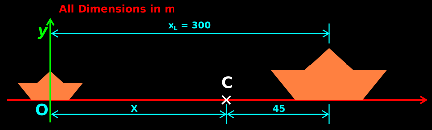
2. Initial position of the 'C' of the two-boat system can be calculated as follows:
• The 'C' is some where on the line joining the two boats
• Assume that the origin O is at the center of the small boat
• This is shown in fig.7.52 below:
• We have: $\mathbf\small{X=\frac{m_S x_S+m_L x_L}{m_S + m_L}}$
• Substituting the known values, we get: $\mathbf\small{X=\frac{m_S \times 0+5400 \times 300}{m_S + 5400}}$
$\mathbf\small{\Rightarrow X=\frac{1620000}{m_S + 5400}}$
3. When the man pulls the boat, the forces involved are internal
• So there is no external force
• So the velocity of the 'C' does not change
• The 'C' was initially at rest (∵ both boats are initially at rest)
• So the 'C' continues to remain at rest. In other words, there is no change in the position of 'C'
4. Finally, when large boat has traveled 45 m, the two boats touch each other
• When the touching happens, both the boats are at 'C'
• That means, the large boat was initially 45 m away from 'C'
• From the fig.7.52, we get: X = (300-45) = 255 m
5. Substituting this value of X in (2), we get: $\mathbf\small{255=\frac{1620000}{m_S + 5400}}$
• Thus we get: mS = 953 kg
Solved example 7.9:
A child sits stationary at one end of a long trolley moving uniformly with a speed V on a smooth horizontal floor. If the child gets up and run about on the trolley in any manner, What is the speed of the CM of the (trolley + child) system?
Solution:
1. The trolley is initially moving with uniform speed
• The floor is smooth. So there is no friction
• That means, there is no external net force on the system
2. When the child begins to run, the forces produced are internal
• Those forces do not contribute any thing towards the external force
• That means, the external force remains zero
■ So, the CM continues to move with the same speed V
Solved example 7.10
A large boat and a small boat are at rest on the surface of a lake. The distance between the two boats is 300 m. A man in the large boat, begins to pull the small boat towards him using a light inextensible rope. When the small boat reaches him, the large boat has moved 45 m towards the small boat. If the large boat has a mass of 5400 kg, what is the mass of the small boat? Neglect the friction offered by the water
Solution:
1. Given:
• Mass of large boat = mL = 5400 kg
• Initial distance between the two boats = 300 m
• Final distance between the two boats = 45 m
• We are asked to find the mass of the small boat mS
2. Initial position of the 'C' of the two-boat system can be calculated as follows:
• The 'C' is some where on the line joining the two boats
• Assume that the origin O is at the center of the small boat
• This is shown in fig.7.52 below:
 |
| Fig.7.52 |
• Substituting the known values, we get: $\mathbf\small{X=\frac{m_S \times 0+5400 \times 300}{m_S + 5400}}$
$\mathbf\small{\Rightarrow X=\frac{1620000}{m_S + 5400}}$
3. When the man pulls the boat, the forces involved are internal
• So there is no external force
• So the velocity of the 'C' does not change
• The 'C' was initially at rest (∵ both boats are initially at rest)
• So the 'C' continues to remain at rest. In other words, there is no change in the position of 'C'
4. Finally, when large boat has traveled 45 m, the two boats touch each other
• When the touching happens, both the boats are at 'C'
• That means, the large boat was initially 45 m away from 'C'
• From the fig.7.52, we get: X = (300-45) = 255 m
5. Substituting this value of X in (2), we get: $\mathbf\small{255=\frac{1620000}{m_S + 5400}}$
• Thus we get: mS = 953 kg
Next we have to learn about angular velocity. For that, first we must be familiar with vector cross products. So we will see that in the next section


