Friday, September 13, 2019

Chapter 7.39 - More Solved examples on Rolling motion

In the previous sectionwe saw rolling along inclined planes. We saw a solved example also. In this section we will see some solved examples related to rolling motion in general.

Solved example 7.52
A disc rotating about its axis with angular speed $\mathbf\small{|\vec{\omega}_0|}$ is placed lightly (without any translational push) on a perfectly frictionless table. The radius of the disc is R. What are the linear velocities of the points A, B and C on the disc shown in fig. 7.148? Will the disc roll in the direction indicated ?
Fig.7.148
Solution:
1. Since there is no friction, the disc will not roll. It will only spin 
• This is because, there is no external force to cause linear motion 
• We have seen the details here.
2. The angular speed will remain the same $\mathbf\small{|\vec{\omega}_0|}$ because, there is no external torque
• When the disc spins with an angular velocity, every point on it will have a certain linear velocity
3. This linear velocity is given by the equation: $\mathbf\small{|\vec{v}|=|\vec{r}|\times|\vec{\omega}|}$
 Where
• $\mathbf\small{|\vec{v}|}$ is the linear velocity of the particle
• $\mathbf\small{|\vec{r}|}$ is the distance of the particle from the center
• $\mathbf\small{|\vec{\omega}|}$ is the angular velocity with which the object rotates about the axis passing through the center
4. So in our present case, we have:
$\mathbf\small{|\vec{v}_A|=R\times|\vec{\omega}_0|}$ (towards right)
$\mathbf\small{|\vec{v}_B|=R\times|\vec{\omega}_0|}$ (towards left)
$\mathbf\small{|\vec{v}_C|=0.5R\times|\vec{\omega}_0|}$ (towards right)

Solved example 7.53
Explain why friction is necessary to make the disc in fig.7.148 roll in the direction indicated
(a) Give the direction of frictional force at B, and the sense of frictional torque, before perfect rolling
begins
(b) What is the force of friction after perfect rolling begins
Solution:
• If there is no friction, the disc will not roll. It will only spin. 
• This is because, there is no external force to cause linear motion
• We have seen the details here
Part (a):
1. The angular velocity is shown in the clockwise direction
• So the disc will move towards the right
2. Initially there is no perfect rolling. There will be slipping
• The friction will be kinetic in nature
• So the direction of the frictional force will be opposite to the direction of motion. That is., towards the left
3. So before perfect rolling, the frictional torque will be acting in the clockwise direction
Part (b):
1. This is a self propagating disc
• Once the perfect rolling begins, the point of contact with the ground will be at rest
2. An external force of friction will come into play only if the disc tries to accelerate
• Since our disc is not accelerating, the frictional force will be zero

Solved example 7.54
A solid cylinder rolls up an inclined plane of angle of inclination 30°. At the bottom of the inclined plane the centre of mass of the cylinder has a speed of 5 m/s.
(a) How far will the cylinder go up the plane?
(b) How long will it take to return to the bottom?
Solution:
1. At the bottom of the inclined plane, the potential energy is zero
2. Calculation of kinetic energy at bottom:
(i) Rotational kinetic energy 
$\mathbf\small{\frac{1}{2}I\,|\vec{\omega}|^2=\frac{1}{2}\left(\frac{m\,R^2}{2}\right)\left(\frac{|\vec{v}_{CM}|}{R}\right)^2=\frac{m|\vec{v}_{CM}|^2}{4}}$ 
• Note that for a solid cylinder, $\mathbf\small{I=\frac{m\,R^2}{2}}$
(ii) Translational kinetic energy = $\mathbf\small{\frac{1}{2}m\,|\vec{v}_{CM}|^2}$
(iii) So total kinetic energy = $\mathbf\small{\frac{m|\vec{v}_{CM}|^2}{4}+\frac{m|\vec{v}_{CM}|^2}{2}=\frac{3m|\vec{v}_{CM}|^2}{4}}$
3. Let the cylinder roll up to a height of 'h' m
• Then the potential energy at that height = mgh
4. Equating the two energies, we get: $\mathbf\small{mgh=\frac{3m|\vec{v}_{CM}|^2}{4}}$
$\mathbf\small{\Rightarrow h=\frac{3|\vec{v}_{CM}|^2}{4g}}$
• Substituting the values, we get: $\mathbf\small{\Rightarrow h=\frac{3(5)^2}{4(9.8)}=1.913\,\rm{m}}$
5. This 'h = 1.913 m' is the vertical distance. It is shown in fig.7.149 below:
Fig.7.149
• The sloping distance 's' can be calculated as follows:
$\mathbf\small{\sin \theta = \frac{h}{s}}$
$\mathbf\small{\Rightarrow \sin 30 =0.5= \frac{1.913}{s}}$
• Thus we get s = 1.9130.5 = 3.826 m
Part (b):
1. The cylinder rolls back down from the height 1.913 m
• Since there is conservation of energy, we can write:
The linear velocity with which the center of the cylinder reaches the bottom will be the same 5 ms-1
• So, for this rolling back motion, the final velocity v is 5 ms-1
2. We have to find the acceleration with which this rolling back occurs
• For a disc and also for a solid cylinder, we have:
Eq.7.40: $\mathbf\small{|\vec{a}|= \frac{2|\vec{g}|\sin \theta}{3}}$
(We derived this equation in the previous section)
Substituting the values, we get: $\mathbf\small{|\vec{a}|= \frac{2(9.8)\sin 30}{3}=3.27}$ ms-2
3. The initial velocity of this back ward rolling is zero
• We can use the equation: $\mathbf\small{|\vec{v}|=|\vec{u}|+|\vec{a}|t}$
• Substituting the values, we get: 5 = 0 + 3.27t
⇒ t = 1.53 s

Solved example 7.55
In the fig.7.150 below, a spring is compressed through a distance of 25 cm using a sphere and then the sphere is let go.
Fig.7.150
(a) What will be the velocity of the center of mass of the sphere when it is at the bottom of the inclined plane ?
(b) What will be the maximum distance traveled by the sphere along the incline ?
Mass of the sphere = 1.5 kg
Radius of the sphere = 8 cm
Spring constant k = 300 N m-1
Solution:
Part (a):
1. When the spring is compressed, 'spring potential energy' is stored up in it
• When the spring is released, the energy becomes available for the sphere
2. Applying law of conservation of energy, we can write: 
Potential energy stored in the spring
= Rotational kinetic energy at B + translational kinetic energy at B
= Potential energy at C
3. Potential energy stored in the spring
$\mathbf\small{\frac{1}{2}kx^2=\frac{1}{2}(300)(0.25)^2=9.375}$ J
4. Rotational kinetic energy at B
= $\mathbf\small{\frac{1}{2}I\,|\vec{\omega}|^2=\frac{1}{2}\left(\frac{2m\,R^2}{5}\right)\left(\frac{|\vec{v}_{CM}|}{R}\right)^2=\frac{m|\vec{v}_{CM}|^2}{5}}$ 
• Note that for a sphere, $\mathbf\small{I=\frac{2m\,R^2}{5}}$
6. Translational kinetic energy at B
$\mathbf\small{\frac{1}{2}m\,|\vec{v}_{CM}|^2}$
7. So we get:
Rotational kinetic energy at B + translational kinetic energy at B
$\mathbf\small{\frac{m|\vec{v}_{CM}|^2}{5}+\frac{m|\vec{v}_{CM}|^2}{2}=\frac{7m|\vec{v}_{CM}|^2}{10}}$
Substituting the values, we get:
$\mathbf\small{\frac{7m|\vec{v}_{CM}|^2}{10}=\frac{7(1.5)|\vec{v}_{CM}|^2}{10}=1.05|\vec{v}_{CM}|^2}$
8. Equating this to the result in (3), we get: $\mathbf\small{1.05|\vec{v}_{CM}|^2=9.375}$
$\mathbf\small{\Rightarrow|\vec{v}_{CM}|=2.99}$ ms-1
Part (b):
1. From (2) in part (a), we have:
Potential energy stored in the spring = Potential energy at C
2. From (3) in part (a), we have:
Potential energy stored in the spring = 9.375 J
3. Potential energy at C
= mgh = (1.5)(9.8)(h) = 14.7 h J
4. Equating the results in (2) and (3), we get: 9.375 = 14.7 h
h = 0.638 m
5. So s = 0.638sin 30 = 1.276 m

Solved example 7.56
A string is wound around a solid cylinder. The free end of the string is attached firmly to the ceiling as shown in fig.7.151 below. The cylinder is let go from a height of h from the ground. What will be the velocity of the CM of the cylinder when it just reaches the ground ?
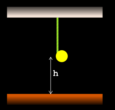
Fig.7.151
Solution:
1. Applying law of conservation of energy, we can write: 
Potential energy of the cylinder at height h
= Rotational kinetic energy of cylinder at ground + translational kinetic energy of cylinder at ground
2. Potential energy of the cylinder when it is at a height h = mgh
3. Rotational kinetic energy at ground
= $\mathbf\small{\frac{1}{2}I\,|\vec{\omega}|^2=\frac{1}{2}\left(\frac{m\,R^2}{2}\right)\left(\frac{|\vec{v}_{CM}|}{R}\right)^2=\frac{m|\vec{v}_{CM}|^2}{4}}$ 
• Note that for a solid cylinder, $\mathbf\small{I=\frac{m\,R^2}{2}}$
4. Translational kinetic energy at B
$\mathbf\small{\frac{1}{2}m\,|\vec{v}_{CM}|^2}$
5. So we get:
Rotational kinetic energy at B + translational kinetic energy at B
$\mathbf\small{\frac{m|\vec{v}_{CM}|^2}{4}+\frac{m|\vec{v}_{CM}|^2}{2}=\frac{3m|\vec{v}_{CM}|^2}{4}}$
6. Equating the energies, we get: $\mathbf\small{mgh=\frac{3m|\vec{v}_{CM}|^2}{4}}$
$\mathbf\small{\Rightarrow|\vec{v}_{CM}|=\sqrt{\frac{4gh}{3}}}$

We have completed a discussion on rotational motion. In the next chapter, we will see gravitation


PREVIOUS           CONTENTS          NEXT

Copyright©2019 Higher Secondary Physics. blogspot.in - All Rights Reserved

Thursday, September 12, 2019

Chapter 7.38 - Rolling along in Inclined planes

In the previous sectionwe saw the maximum force that can be applied on a wheel which is not able to self propagate. In this section we will see the case of objects rolling along inclined planes

1. Consider the disc shown in fig.7.147 (a) below
Fig.7.147(a)
• It has a mass m and radius R
• It is rolling down an inclined plane. The angle of inclination is θ
■ We want the disc to have 'pure rolling'. That is., there must not be any slip
2. This disc is not able to self propagate because there is no engine attached
• But it's self weight will cause it to move
• This will be clear when we draw all the force vectors acting on the wheel. They are shown in fig.b
We have:
(i) The weight $\mathbf\small{m|\vec{g}|}$ acting downwards from the center C
    ♦ The component $\mathbf\small{m|\vec{g}|\cos \theta}$ acts parallel to the inclined plane
    ♦ The component $\mathbf\small{m|\vec{g}|\sin \theta}$ acts perpendicular to the inclined plane
(ii) The normal reaction $\mathbf\small{|\vec{N}|}$ acting perpendicular to the plane
    ♦ This acts at the point of contact
    ♦ The magnitude is equal to $\mathbf\small{m|\vec{g}|\cos \theta}$  
(This force is not shown in the fig)
(iii) The frictional force  $\mathbf\small{|\vec{f_s}|=\mu_s|\vec{N}|=\mu_sm|\vec{g}|\cos \theta}$
    ♦ This force acts parallel to the inclined plane 
• Note that, we use the 𝝁s instead of 𝝁k because, we want pure rolling
• Also recall that, when there is no self propagation, the frictional force will be opposite to the direction of motion
3. Our aim is to find the maximum force acting on the disc so that no slipping occurs
• We will separate the calculations into two sets:
Set 1 comprises of the calculations related to rotation
Set 2 comprises of the calculations related to translation
4. Set 1:
(i) If there is a rolling motion, there has to be a torque
• This torque is provided by the frictional force $\mathbf\small{|\vec{f_s}|}$
• Because, all other forces are acting through the center of the wheel
• So we have: $\mathbf\small{|\vec{\tau}|=|\vec{f_s}|R=\mu_sm|\vec{g}|R \cos \theta}$
• $\mathbf\small{\mu_sm|\vec{g}|R \cos \theta}$ is the maximum frictional force possible
• So we can write: $\mathbf\small{|\vec{\tau}_{max}|=\mu_sm|\vec{g}|R \cos \theta}$
(ii) But $\mathbf\small{|\vec{\tau}|=I\,|\vec{\alpha}|}$
• Where:
    ♦ $\mathbf\small{I}$ is the moment of inertia of the wheel
    ♦ $\mathbf\small{|\vec{\alpha}|}$ is the angular acceleration of the wheel
(iii) For pure rolling, we have Eq.7.36 that we derived in the previous section: $\mathbf\small{|\vec{a}|=R\,|\vec{\alpha}|}$
• Rearranging this, we get: $\mathbf\small{|\vec{\alpha}|=\frac{|\vec{a}|}{R}}$
(iv) For our present case, we must consider the maximum allowable angular acceleration
• So we must denote it as $\mathbf\small{|\vec{\alpha}_{max}|}$
• So we have: $\mathbf\small{|\vec{\alpha}_{max}|=\frac{|\vec{a}_{max}|}{R}}$
(v) Thus from (ii), we get: $\mathbf\small{|\vec{\tau}_{max}|=I\,\frac{|\vec{a}_{max}|}{R}}$
• We know the I of the disc: $\mathbf\small{I=\frac{mR^2}{2}}$
• So we get: $\mathbf\small{|\vec{\tau}_{max}|=\left(\frac{mR^2}{2}\right)\,\frac{|\vec{a}_{max}|}{R}=\frac{mR|\vec{a}_{max}|}{2}}$  
(vi) So the result in (i) becomes: $\mathbf\small{\frac{mR|\vec{a}_{max}|}{2}=\mu_sm|\vec{g}|R \cos \theta}$
• From this we get: $\mathbf\small{|\vec{a}_{max}|= 2\mu_s|\vec{g}|\cos \theta}$
5. Set 2:
 We have: Net force = mass × acceleration
• In our present case:
Net force = $\mathbf\small{m|\vec{g}|\sin \theta-|\vec{f_s}|}$
= $\mathbf\small{m|\vec{g}|\sin \theta-\mu_s\,m|\vec{g}|\cos \theta}$
$\mathbf\small{m|\vec{a}_{max}|}$
6. The two sets are complete
• We take the result from Set 1 (vi)
• And apply it in the result from Set 2
• We get:
Net force 
$\mathbf\small{m|\vec{g}|\sin \theta-\mu_s\,m|\vec{g}|\cos \theta}$
$\mathbf\small{m\times 2\mu_s|\vec{g}|\cos \theta}$
$\mathbf\small{\Rightarrow m|\vec{g}|\sin \theta=3\mu_s\,m|\vec{g}|\cos \theta}$   
7. The quantity $\mathbf\small{|\vec{F}_{max}|}$ is the force that causes the disc to roll
• It is denoted as $\mathbf\small{|\vec{F}_{max}|}$  
8. Thus we get:
Eq.7.38: 
For a disc rolling down an inclined plane:
$\mathbf\small{|\vec{F}_{max}|}$
= $\mathbf\small{m|\vec{g}|\sin \theta}$
= $\mathbf\small{m\times2\mu_s|\vec{g}|\cos \theta+m\times\mu_s|\vec{g}|\cos \theta=3\mu_sm|\vec{g}|\cos \theta}$
= $\mathbf\small{3\mu_sm|\vec{g}|\cos \theta}$
• Note that, this equation is valid only for a disc and a solid cylinder. For other types of objects, suitable equations must be derived using the appropriate values of I 
9. We see that $\mathbf\small{m|\vec{g}|\sin \theta}$ is the force that causes the disc to move
• This $\mathbf\small{m|\vec{g}|\sin \theta}$ must not exceed a 'certain value'
• This 'certain value' is: $\mathbf\small{3\mu_sm|\vec{g}|\cos \theta}$
10. So we can write:
$\mathbf\small{m|\vec{g}|\sin \theta}$ should always be less than or equal to $\mathbf\small{3\mu_sm|\vec{g}|\cos \theta}$
• That is: $\mathbf\small{m|\vec{g}|\sin \theta\;\;\leq \;\;3\mu_sm|\vec{g}|\cos \theta}$  
• Where
    ♦ $\mathbf\small{m|\vec{g}|\sin \theta}$ is the actual force acting
    ♦ $\mathbf\small{3\mu_sm|\vec{g}|\cos \theta}$ is the maximum allowable force
11. If the left side ever becomes greater than the right side, we will have to make adjustments
• We cannot change mass because, it occurs on both sides
• We see that 𝝁s occurs on the right side only
• So, if the left side increases beyond the limit, we can increase the right side by increasing 𝝁s.
An example:
• m = 5 kg, θ = 35o and 𝝁s = 0.2
Then:
(i) Actual force acting = $\mathbf\small{m|\vec{g}|\sin \theta}$ = 28.1 N
(ii) Maximum allowable force = $\mathbf\small{3\mu_sm|\vec{g}|\cos \theta}$ = 24.1 N
(iii) We have to increase (ii). For that, we will increase the 𝝁s. This can be achieved by increasing the roughness of surface
(iv) But what must be the new value of 𝝁s ?
• To find that, we consider the inequality:
$\mathbf\small{m|\vec{g}|\sin \theta\;\;\leq \;\;3\mu_sm|\vec{g}|\cos \theta}$
• If we multiply or divide both sides of an inequality by a same quantity, the 'inequality' will not change
(v) Here, we will divide both sides by $\mathbf\small{m|\vec{g}|\cos \theta}$. We get:
$\mathbf\small{\tan \theta\;\;\leq \;\;3\mu_s}$
• Dividing both sides by 3, we get:
$\mathbf\small{\frac{\tan \theta}{3}\;\;\leq \;\;\mu_s}$
(vi) That means 𝝁s must be just greater than $\mathbf\small{\frac{\tan \theta}{3}}$
• If this condition is satisfied, the allowable force will be just sufficient
12. So for our present case, 𝝁s must be just greater than (tan 353) = 0.233
• Let us provide a 𝝁s of 0.25   
13. Let us check with the new data:
• m = 5 kg, θ = 35o and 𝝁s = 0.25
Then:
(i) Actual force acting = $\mathbf\small{m|\vec{g}|\sin \theta}$ = 28.1 N
(ii) Maximum allowable force = $\mathbf\small{3\mu_sm|\vec{g}|\cos \theta}$ = 30.1 N
Note: In actual situations, various safety factors must be multiplied to the newly obtained 𝝁sOnly then it will be considered safe. We will learn about them in higher classes 
14. If the 𝝁s cannot be changed, then the only option is to change θ 
(i) To find the new value of θ, we consider the inequality:
$\mathbf\small{m|\vec{g}|\sin \theta\;\;\leq \;\;3\mu_sm|\vec{g}|\cos \theta}$
• If we multiply or divide both sides of an inequality by a same quantity, the 'inequality' will not change
(ii) Here, we will divide both sides by $\mathbf\small{m|\vec{g}|\cos \theta}$. We get:
$\mathbf\small{\tan \theta\;\;\leq \;\;3\mu_s}$
Thus we get:
7.39: $\mathbf\small{\theta\;\;\leq \;\;\tan^{-1}(3\mu_s)}$
• Note that, this relation is valid only for a disc and a solid cylinder. For other types of objects, suitable relations must be derived using the appropriate values of I
(iii) That means, θ should be brought down so that, it is just less than $\mathbf\small{tan^{-1}(3\mu_s)}$
(iv) If this condition is satisfied, the allowable force will be just sufficient
15. So for our present case, θ must be just less than [tan-1 (3 × 0.2)] = 30.96o
• Let us provide a θ of 30
16. Let us check with the new data:
• m = 5 kg, θ = 30o and 𝝁s = 0.2
Then:
(i) Actual force acting = $\mathbf\small{m|\vec{g}|\sin \theta}$ = 24.5 N
(ii) Maximum allowable force = $\mathbf\small{3\mu_sm|\vec{g}|\cos \theta}$ = 25.5 N
Note: In actual situations, various safety factors must be multiplied to the newly obtained θ. Only then it will be considered safe. We will learn about them in higher classes

Let us write a summary of the above discussion. The summary can be written in 3 steps:
1. We have a disc rolling down an inclined plane
• From the given data, we are  able to find the following items:
(i) The maximum force that will be causing the motion:
$\mathbf\small{|\vec{F}_{max}|}$ = $\mathbf\small{m|\vec{g}|\sin \theta}$
(ii) The maximum allowable force:
$\mathbf\small{3\mu_sm|\vec{g}|\cos \theta}$
• Using the above two items, we can determine whether the disc will slip or not 
2. The condition at which the two items become equal is the 'limiting condition'
• At that condition, 'maximum allowable net force' will be acting on the disc
• This is given by: Net force = $\mathbf\small{m|\vec{g}|\sin \theta-|\vec{f_s}|}$
= $\mathbf\small{m|\vec{g}|\sin \theta-\mu_s\,m|\vec{g}|\cos \theta}$ 
3. That means, at that condition, the disc will be experiencing $\mathbf\small{|\vec{a}_{max}|}$ the 'maximum allowable linear acceleration' 
• And we know the method to find that maximum allowable linear acceleration:
$\mathbf\small{|\vec{a}_{max}|= 2\mu_s|\vec{g}|\cos \theta}$

1. But what if the disc is rolling well within the limit?
This will occur under the following conditions:
• 𝝁s is greater than the limiting value
or
• θ is less than the limiting value   
2. In such a situation, the acceleration $\mathbf\small{|\vec{a}|}$  experienced by the disc will be less than $\mathbf\small{|\vec{a}_{max}|}$
3. In such a situation, the force ($\mathbf\small{m|\vec{g}|\sin \theta}$) which causes motion of the disc will be well within the safe limit
4. We want to know the $\mathbf\small{|\vec{a}|}$ in such a situation
5. This is a special situation
The reason for the situation becoming 'special' can be written in 6 steps:
(i) We usually calculate the static frictional force using 𝝁s 
(ii) But such a calculation gives the 'maximum static frictional force which is possible'
(iii) When the disc is rolling well with in the safe limit, this maximum static frictional force will not be acting on it
(iv) Because, we know that, static friction is a self adjusting force
    ♦ It increases when the applied force increases
    ♦ It decreases when the applied force decreases
■ Here we experience the difference between rolling motion and sliding motion
• The sliding motion begins only when the full available frictional force is exceeded
• The rolling motion does not wait for 'the full available frictional force to be exceeded'
(v) In our present case, the applied force $\mathbf\small{m|\vec{g}|\sin \theta}$ is so less that, the full static frictional force is not mobilized
• So we do not know exactly how much static friction is acting  
• So we cannot use 𝝁s
6. However, we can derive a formula, which does not involve the coefficient
We will separate the calculations into two sets:
• Set 1 comprises of the calculations related to rotation
• Set 2 comprises of the calculations related to translation
7. Set 1:
(i) $\mathbf\small{|\vec{\tau}|=I|\vec{\alpha}|=\frac{mR^2}{2}|\vec{\alpha}|=\frac{mR^2}{2}\times\frac{|\vec{a}|}{R}=\frac{mR|\vec{a}|}{2}}$
(ii) But $\mathbf\small{|\vec{\tau}|=\mu m|\vec{g}|\cos \theta \times R}$
(iii) Equating the results, we get: $\mathbf\small{|\vec{\tau}|=\mu\,m|\vec{g}|\cos \theta \times R=\frac{mR|\vec{a}|}{2}}$
$\mathbf\small{\Rightarrow \mu|\vec{g}|\cos \theta=\frac{|\vec{a}|}{2}}$
8. Set 2:
Net force = $\mathbf\small{m|\vec{g}|\sin \theta-\mu\;m|\vec{g}|\cos \theta=m|\vec{a}|}$
9. The two sets are complete
• Now we take the result from Set 1 (iii) 
• And apply it in the result from Set 2
We get:
Net force = $\mathbf\small{m|\vec{g}|\sin \theta-m\times\frac{|\vec{a}|}{2}=m|\vec{a}|}$
$\mathbf\small{\Rightarrow m|\vec{g}|\sin \theta=\frac{3m|\vec{a}|}{2}}$
$\mathbf\small{\Rightarrow |\vec{a}|=\frac{2|\vec{g}|\sin \theta}{3}}$
10. We can write:
When a disc is rolling down an incline with out slipping, the linear acceleration is given by:
Eq.7.40: $\mathbf\small{|\vec{a}|=\frac{2|\vec{g}|\sin \theta}{3}}$
• Note that, this equation is valid only for a disc and a solid cylinder. For other types of objects, suitable equations must be derived using the appropriate values of I

Solved example 7.51
A cylinder of mass 10 kg and radius 15 cm is rolling perfectly on a plane of inclination 30o. The coefficient of static friction  𝝁s = 0.25.
(a) How much is the force of friction acting on the cylinder ?
(b) What is the work done against friction during rolling ?
(c) If the inclination θ of the plane is increased, at what value of θ does the cylinder begin to skid,
and not roll perfectly ?
Solution:
• Both solid cylinder and disc have the same I. So the equations that we derived above are applicable for this problem
• First we need to know whether the maximum frictional force is mobilized or not
• For that we do the following 4 steps:
1. We will use the relation in Eq.7.38: For a disc rolling down an inclined plane:
$\mathbf\small{|\vec{F}_{max}|}$ = $\mathbf\small{m|\vec{g}|\sin \theta}$
• This maximum force must be less than or equal to $\mathbf\small{3\mu_sm|\vec{g}|\cos \theta}$ 
2. Substituting the values we get:
$\mathbf\small{m|\vec{g}|\sin \theta=49\,\rm{N}}$
3. Similarly, we get: $\mathbf\small{3\mu_sm|\vec{g}|\cos \theta=63.65\,\rm{N}}$
4. Result in (2) is less than the result in (3)
• So it is safe. The cylinder will not slip. Also there is no need to mobilize the maximum available frictional force
• Now we can find the answers to the given questions
Part (a):
1. To find the actual acceleration, we use
Eq.7.40: $\mathbf\small{|\vec{a}|=\frac{2|\vec{g}|\sin \theta}{3}}$
• Substituting the values, we get: $\mathbf\small{|\vec{a}|=3.27\,\rm{m\,s^{-2}}}$
2. We have:
Net force = Force acting downwards along the slope - Frictional force
⇒ Net force = [$\mathbf\small{m|\vec{g}|\sin \theta}$ - Frictional force]
⇒ Net force = [49 - Frictional force]
3. But net force = Mass × acceleration = (10 × 3.27) = 32.7 N
4. So the result in (2) becomes:
32.7 = [49 - Frictional force]
⇒ Frictional force = 49 - 32.7 = 16.3 N
Part (b):
1. We have: Work done = Force × Displacement   
2. The frictional force acts on every particle on the periphery of the cylinder
3.  Consider the instant at which a particle experiences the frictional force
• At that instant, the displacement of that particle is zero
• At the next instant, the frictional force no longer acts on that particle
    ♦ Because, the succeeding particle takes up it's position
4. So displacement is always zero
5. So no work is done against the frictional force
Part (c):
• We will use the relation in 7.39: $\mathbf\small{\theta\;\;\leq \;\;\tan^{-1}(3\mu_s)}$
• Substituting the values we get: θ ≤ tan-1 (3 × 0.25)
⇒ θ ≤ tan-1 (0.75)
⇒ θ  36.87
• So if θ is greater than 36.87o, the cylinder will begin to skid

We have completed a discussion on rolling motion. In the next section, we will see a few more solved examples


PREVIOUS           CONTENTS          NEXT

Copyright©2019 Higher Secondary Physics. blogspot.in - All Rights Reserved

Sunday, September 8, 2019

Chapter 7.37 - Maximum allowable force on Cart wheels

In the previous sectionwe saw the maximum acceleration with which a car can be set into motion. In this section we will see the case of a cart. 
• We have seen that, a cart needs external force to move. If this force is too large, the wheels will slip
• So there is a maximum allowable force. Our next aim is to find the magnitude of this allowable force

1. Consider the wheel shown in fig.7.146(a) below
It has a mass of 7 kg. It's radius is 0.35 m
Fig.7.146
𝝁s = 0.8 and 𝝁k = 0.6
2. A force is being applied at it's center
• This force is denoted as $\mathbf\small{|\vec{F}_{max}|}$
• This is because, it is the maximum force allowable. If a greater force is applied, the wheel will slide instead of rolling
3. Fig.b shows the remaining forces also which are acting on the wheel
• The weight $\mathbf\small{m|\vec{g}|}$ acts downwards at the center
• The normal force $\mathbf\small{|\vec{N}|}$ acts upwards from the point of contact with the ground
• We have the frictional force $\mathbf\small{|\vec{f_s}|=\mu_s|\vec{N}|=\mu_sm|\vec{g}|}$
• We use the static friction because, we want the wheel to be in 'pure rolling' motion
• Also we know that, for a cart wheel, the frictional force is opposite to the direction of motion
4. This frictional force is the 'cause of the torque' which rotates the wheel
• Because, it is the only force which does not pass through the center of the wheel
5. Now we will do the further calculations as two sets
Set 1 is related to rotational motion
Set 2 is related to translational motion
6. Set 1:
(i) The frictional force is the 'cause of the torque'
• So we have: $\mathbf\small{|\vec{\tau}|=|\vec{f_s}|R=\mu_sm|\vec{g}|R}$
• $\mathbf\small{\mu_sm|\vec{g}|R}$ is the maximum frictional force possible
• So we can write: $\mathbf\small{|\vec{\tau}_{max}|=\mu_sm|\vec{g}|R}$
(ii) But $\mathbf\small{|\vec{\tau}|=I\,|\vec{\alpha}|}$
• Where:
    ♦ $\mathbf\small{I}$ is the moment of inertia of the wheel
    ♦ $\mathbf\small{|\vec{\alpha}|}$ is the angular acceleration of the wheel
(iii) For pure rolling, we have eq.7.36 that we derived in the previous section: $\mathbf\small{|\vec{a}|=R\,|\vec{\alpha}|}$
• Rearranging this, we get: $\mathbf\small{|\vec{\alpha}|=\frac{|\vec{a}|}{R}}$
(iv) For our present case, we must consider the maximum allowable angular acceleration
• So we must denote it as $\mathbf\small{|\vec{\alpha}_{max}|}$
• So we have: $\mathbf\small{|\vec{\alpha}_{max}|=\frac{|\vec{a}_{max}|}{R}}$
(v) Thus from (ii), we get: $\mathbf\small{|\vec{\tau}_{max}|=I\,\frac{|\vec{a}_{max}|}{R}}$
• Now, assuming the I of the wheel to be the same as that of the disc, we have: $\mathbf\small{I=\frac{mR^2}{2}}$
• So we get: $\mathbf\small{|\vec{\tau}_{max}|=\left(\frac{mR^2}{2}\right)\,\frac{|\vec{a}_{max}|}{R}=\frac{mR|\vec{a}_{max}|}{2}}$  
(vi) So the result in (i) becomes: $\mathbf\small{\frac{mR|\vec{a}_{max}|}{2}=\mu_sm|\vec{g}|R}$
• From this we get: $\mathbf\small{|\vec{a}_{max}|= 2\mu_s|\vec{g}|}$
7. Set 2:
We have: Net force = mass × acceleration
• In our present case, Net force = $\mathbf\small{|\vec{F}_{max}|-|\vec{f_s}|}$
⇒ Net force = $\mathbf\small{|\vec{F}_{max}|-\mu_s\,m|\vec{g}|}$
8. The two sets are complete
• Now we take the result from set 1 (vi)
• And apply it in the result from set 2
• We get:
Net force = $\mathbf\small{|\vec{F}_{max}|-\mu_s\,m|\vec{g}|=m\times2\mu_s|\vec{g}|}$
• Thus we get:
Eq.7.37: $\mathbf\small{|\vec{F}_{max}|=m\times2\mu_s|\vec{g}|+\mu_s\,m|\vec{g}|=3\mu_sm|\vec{g}|}$ 
Substituting the values, we get: $\mathbf\small{|\vec{F}_{max}|}$ = 3 × 0.8 × × 9.8 = 164.64 N

Now we will see a solved example
Solved example 7.49
The wheel shown in fig.7.146(c) above, has a radius of 0.35 m and a mass of 6 kg. A horizontal force of 85 N is applied at it's center. What is the linear acceleration of the wheel?  𝝁s = 0.4 and 𝝁k = 0.3
Take g = 9.8 ms-2  
Solution
1. First of all, we have to determine whether the wheel would slip or not, when the 85 N is applied
• For that, we find the maximum allowable force $\mathbf\small{|\vec{F}_{max}|}$ 
• If 85 N is greater than this maximum allowable force, the wheel will slip
2. We have Eq.7.37: $\mathbf\small{|\vec{F}_{max}|=m\times2\mu_s|\vec{g}|+\mu_s\,m|\vec{g}|=3\mu_sm|\vec{g}|}$
• Substituting the values, we get: $\mathbf\small{|\vec{F}_{max}|}$ = 3 × 0.4 × 6 × 9.8 = 70.56 N
3. So the applied force of 85 N is greater than the maximum allowable force. So the wheel will slip
4. If the wheel slips, static friction is not valid any more. We must consider only kinetic friction
• The kinetic frictional force acting on the wheel = $\mathbf\small{|\vec{f_s}|=\mu_km|\vec{g}|}$ 
• Substituting the values, we get:
Kinetic friction acting on the wheel = 0.3 × 6 × 9.8 = 17.64 N
5. So the net force acting on the wheel = (85 - 17.64) = 67.36 N
6. We have: Net force = mass × acceleration
• Thus we get: Acceleration of the wheel = Net forcemass 67.3611.23 ms-2.

Solved example 7.50
A horizontal force F acts at the center of a sphere of mass m. The coefficient of static friction between the sphere and the ground is 𝝁. What is the maximum allowable value of F so that, the sphere rolls without slipping ?
Solution:
1. Let f be the force of friction. it acts opposite to the direction of motion
• So the net force acting on the sphere = F-f
2. So the acceleration of the sphere = $\mathbf\small{a=\frac{F-f}{m}}$
3. For pure rolling, we have: $\mathbf\small{a=R\alpha}$
4. But $\mathbf\small{\alpha=\frac{\tau}{I}}$
$\mathbf\small{\Rightarrow\alpha=\frac{fR}{\frac{2mR^2}{5}}=\frac{5f}{2mR}}$
5. So from (3) we get: $\mathbf\small{a=r\alpha=R\times\frac{5f}{2mR}=\frac{5f}{2m}}$
6. So from (2), we get: $\mathbf\small{a=\frac{F-f}{m}=\frac{5f}{2m}}$
$\mathbf\small{\Rightarrow{F-f}=\frac{5f}{2}}$
$\mathbf\small{\Rightarrow F=\frac{7f}{2}}$
7. But f = 𝝁mg
So the result in (6) becomes: $\mathbf\small{F=\frac{7\mu\,mg}{2}}$
8. Thus we can write:
The applied force must be less than or equal to $\mathbf\small{\frac{7\mu\,mg}{2}}$

So we have completed a discussion on the rotation of cart wheels which needs external force to propagate. Analysis of such wheels are applicable to 'front wheels of cars' also. In the next section, we will see the case of rolling along inclined planes


PREVIOUS           CONTENTS          NEXT

Copyright©2019 Higher Secondary Physics. blogspot.in - All Rights Reserved

Thursday, September 5, 2019

Chapter 7.36 - Acceleration of a Car

In the previous sectionwe saw the case of a car in which the real wheels are self propagating. We also saw the case of a cart whose wheels need external force to rotate

1. Consider an independent circular disc. The word 'independent' is specified to clarify that, the disc has no external connections like to an axle or an engine
• It is kept at a height away from the ground. This is shown in fig.7.145 (a) below:
Fig.7.145
2. Assume that this disc has the ability to self propagate. Like a rear car wheel
• So let it spin. When it has attained considerable  angular speed, say $\mathbf\small{\vec{\omega}_i}$, stop the engine
3. If there is no frictional resistance or air resistance, that disc will continue to spin for ever with angular velocity $\mathbf\small{\vec{\omega}_i}$
• We know the reason:
If there is no external torque, angular momentum $\mathbf\small{I\vec{\omega}_i}$ will be conserved
4. Lower the disc slowly so that the disc gently touches the floor
• Care should be taken to ensure that, while placing the disc, no horizontal force is produced on the disc
5. Assume that the floor is a rough surface
• So there will be friction between the disc and the floor
• In the previous section, we have seen that in the case of a self propagating disc, the frictional force will be in the direction of motion
6. We have to determine whether this friction is static or kinetic
(i) The disc is continuously spinning. There is no instant at which any point on the periphery is at rest
(ii) Let the point of contact be P
(iii) Consider the instant at which the contact with the floor takes place. Even at that instant, the particle P is in motion
(iv) If it is to be at rest, the following two velocities must be equal:
    ♦ The tangential velocity of P, which is towards the left
    ♦ The velocity of the center of mass C, which is towards the right
(v) But at the instant of touch down, the 'velocity of the center of mass towards the right' is zero
(vi) So the point of contact is not at rest at the instant of touch down
(vii) So the frictional force is that of kinetic friction
(viii) This is shown as $\mathbf\small{|\vec{f_k}|}$ in the fig.b
7. The $\mathbf\small{|\vec{f_k}|}$ is acting on the disc. That means an external force is acting on the disc
• So the center of mass of the disc will have linear acceleration $\mathbf\small{|\vec{a}|}$ 
• We have: Force = mass × acceleration
So this acceleration can be obtained using the expression: $\mathbf\small{|\vec{a}|=\frac{|\vec{f_k}|}{m}}$
8. Note: For translational motion, we assume that the external net force acts at the center of mass
• So in our present case, the $\mathbf\small{\vec{f_k}}$ can be assumed to be acting at the center of the disc
• So the expression written in (7) is valid
9. Thus we obtained the linear acceleration $\mathbf\small{|\vec{a}|}$
• The initial linear velocity $\mathbf\small{|\vec{v}_i|}$ is zero
• So the linear velocity $\mathbf\small{|\vec{v}_{(t)}|}$ after a time interval of 't' s after touch down will be given by:
$\mathbf\small{|\vec{v}_{(t)}|=|\vec{v}_i|+|\vec{a}|\,t}$
$\mathbf\small{\Rightarrow|\vec{v}_{(t)}|=0+|\vec{a}|\,t}$
$\mathbf\small{\Rightarrow|\vec{v}_{(t)}|=|\vec{a}|\,t}$
10. Next we consider the angular motion
• The force $\mathbf\small{\vec{f_k}}$ acts on the disc
• But $\mathbf\small{\vec{f_k}}$ it does not pass through the center of the disc
• So the disc will experience a torque
• Obviously, this torque is given by: $\mathbf\small{|\vec{\tau}|=|\vec{f_k}|\,R}$ 
11. If there is a torque, there will be an acceleration $\mathbf\small{|\vec{\alpha}|}$
• This $\mathbf\small{|\vec{\alpha}|}$ can be obtained using the expression: $\mathbf\small{|\vec{\alpha}|=\frac{|\vec{\tau}|}{I}}$
• Recall that $\mathbf\small{\vec{\tau}=I\,\vec{\alpha}}$ corresponds to $\mathbf\small{\vec{F}=m\,\vec{a}}$
12. Thus we obtained the angular acceleration $\mathbf\small{|\vec{\alpha}|}$
• The initial angular speed is $\mathbf\small{\vec{\omega}_i}$
• So the angular speed $\mathbf\small{|\vec{\omega}_{(t)}|}$ after a time interval of 't' s after touch down will be given by:
$\mathbf\small{|\vec{\omega}_{(t)}|=|\vec{\omega}_i|-|\vec{\alpha}|\,t}$
■ Why is a negative sign given to $\mathbf\small{|\vec{\alpha}|}$?
• The answer can be written in 5 steps:
(i) The torque is created by $\mathbf\small{\vec{f_k}}$
(ii) From the direction of $\mathbf\small{\vec{f_k}}$, it is obvious that, the torque opposes the initial angular velocity
(iii) That means, the angular speed will go on decreasing
(iv) That means, there is angular 'deceleration'
(v) So we give a negative sign  
13. Let us write the two available equations together:
• From (9), we have: $\mathbf\small{|\vec{v}_{(t)}|=|\vec{a}|\,t}$ 
• From (12), we have: $\mathbf\small{|\vec{\omega}_{(t)}|=|\vec{\omega}_i|-|\vec{\alpha}|\,t}$
14. The rolling of the disc just after touch down is not 'pure rolling'
    ♦ We proved this by showing that the velocity of the contact point P is not zero
• We also saw in (12) that, the disc suffers angular deceleration
    ♦ So a time will come at which the angular velocity becomes so low that, the condition $\mathbf\small{|\vec{v}_{CM}|=R\,|\vec{\omega}|}$ is satisfied
    ♦ At that time, the rolling changes to pure rolling
Let the pure rolling begin after 't' seconds
• For pure rolling, we have: $\mathbf\small{|\vec{v}_{CM}|=R\,|\vec{\omega}|}$
• All points of the disc will have the same linear velocity $\mathbf\small{|\vec{v}_{CM}|}$
• So we can simply write $\mathbf\small{|\vec{v}|}$ instead of $\mathbf\small{|\vec{v}_{CM}|}$
• So we can write as:
When pure rolling begins: $\mathbf\small{|\vec{v}_{(t)}|=R\,|\vec{\omega}_{(t)}|}$
15. Now we substitute for $\mathbf\small{|\vec{v}_{(t)}|}$ and $\mathbf\small{|\vec{\omega}_{(t)}|}$ 
• We use the equations in (13) for the substitution. We get:
$\mathbf\small{|\vec{a}|\,t=R\,\left(|\vec{\omega}_i|-|\vec{\alpha}|\,t\right)}$
$\mathbf\small{\Rightarrow|\vec{a}|\,t=R|\vec{\omega}_i|-R|\vec{\alpha}|\,t}$
$\mathbf\small{\Rightarrow(|\vec{a}|+R|\vec{\alpha}|)\,t=R|\vec{\omega}_i|}$
• Thus we get:
Eq.7.35: $\mathbf\small{t= \frac{R|\vec{\omega}_i|}{(|\vec{a}|+R|\vec{\alpha}|)}}$
• Where:
    ♦ t is the time after which pure rolling begins
    ♦ R is the radius of the disc
    ♦ $\mathbf\small{|\vec{\omega}_i|}$ is the angular velocity at the time of touch down
    ♦ $\mathbf\small{|\vec{a}|=\frac{|\vec{f_k}|}{m}}$
    ♦ $\mathbf\small{|\vec{\alpha}|=\frac{|\vec{\tau}|}{I}=\frac{R\,|\vec{f_k}|}{I}}$

We will see a solved example:
Solved example 7.46
A wheel spinning at an angular velocity of 70 rad s-1 is slowly lowered on to the ground with out any horizontal force. Radius of the wheel is 0.4 m and it's mass is 15 kg. 
(a) After what time will the pure rolling begin? 
(b) What is the distance traveled by the wheel before the beginning of pure rolling ?
Coefficient of kinetic friction between the wheel and the ground is 0.5
Take g = 9.8 ms-2  
Solution:
Part (a):
1. We have Eq.7.35: $\mathbf\small{t= \frac{R|\vec{\omega}_i|}{(|\vec{a}|+R|\vec{\alpha}|)}}$
2. Calculation of $\mathbf\small{|\vec{a}|}$:
• $\mathbf\small{|\vec{a}|=\frac{|\vec{F}|}{m}=\frac{|\vec{f_k}|}{m}=\frac{\mu_k\,m\,|\vec{g}|}{m}=\mu_k|\vec{g}|}$
• So we get: $\mathbf\small{|\vec{a}|=\mu_k|\vec{g}|=(0.5 \times 9.8)}$ = 4.9 ms-2 
3. Calculation of $\mathbf\small{|\vec{\alpha}|}$:
• $\mathbf\small{|\vec{\alpha}|=\frac{|\vec{\tau}|}{I}=\frac{R\,|\vec{f_k}|}{I}}$
• For a disc $\mathbf\small{I=\frac{mR^2}{2}}$
• So we get: $\mathbf\small{|\vec{\alpha}|=\frac{2R\,|\vec{f_k}|}{mR^2}=\frac{2\,|\vec{f_k}|}{mR}}$
$\mathbf\small{\Rightarrow|\vec{\alpha}|=\frac{2\,\mu_k\,m\,|\vec{g}|}{mR}=\frac{2\,\mu_k\,|\vec{g}|}{R}}$
$\mathbf\small{\Rightarrow|\vec{\alpha}|=\frac{2(0.5)(9.8)}{0.4}=25.4}$ rad s-2.
4. Substituting the results from (2) and (3) in (1), we get:
$\mathbf\small{t= \frac{0.4 \times 70}{[(4.9)+0.4(25.4)]}=1.86\, \rm{s}}$

Part (b):
1. Consider the two instances:
(i) Instance at which the contact with the floor is made
(ii) Instance at which the pure rolling begins
2. From part (a), we have: Time interval between the two instances = 1.86 s
• Linear acceleration with which the wheel travels during this time interval = (0.5 × 9.8) = 4.9 ms-2.
• Initial velocity of this linear motion = 0
• So we can find the velocity at the instance when pure rolling begins 
3. We can use the relation $\mathbf\small{|\vec{v}_f|=|\vec{v}_i|+|\vec{a}|\,t}$
• For our present case: $\mathbf\small{|\vec{v}_f|=0+|\vec{a}|\,t}$
$\mathbf\small{\Rightarrow|\vec{v}_f|=|\vec{a}|\,t}$
• Substituting the values, we get: $\mathbf\small{|\vec{v}_f|}$ = (4.9 × 1.86) = 9.114 ms-1.
4. Let $\mathbf\small{|\vec{x}|}$ be the distance traveled by the wheel during this interval
• We can use the relation: $\mathbf\small{|\vec{v}_f|^2-|\vec{v}_i|^2=2|\vec{a}|\,|\vec{x}|}$
• Substituting the values, we get: $\mathbf\small{9.1^2-0=2\times4.9\times|\vec{x}|}$
• Thus we get: $\mathbf\small{|\vec{x}|}$ = 8.45 m

Solved example 7.47
A solid disc and a ring, both of radius 10 cm are placed on a horizontal table simultaneously, with initial angular speed equal to 10 𝝅 rad s-1. Which of the two will start to roll earlier ? The co-efficient of kinetic friction is 𝝁k = 0.2
Solution:
• The solid disc and ring are placed simultaneously
• Both have the same initial angular velocity of 10 𝝅 rad s-1 
• As soon as they are placed, both will move horizontally in the same direction
• But for both of them, this motion will not be 'pure rolling'
• Pure rolling will start only after some time 't' after the 'instant of touch down'
• This 't' will be different for the two objects
• We have to find which object has the smallest 't'
• Given that the radius is the same 10 cm for both the objects. So we will write: 
    ♦ Radius of disc = Radius of ring = R = 10 cm
1. First we will consider the solid disc
We have:
Eq.7.35: $\mathbf\small{t= \frac{R|\vec{\omega}_i|}{(|\vec{a}|+R|\vec{\alpha}|)}}$
• Where:
    ♦ t is the time after which pure rolling begins
    ♦ R is the radius of the disc
    ♦ $\mathbf\small{|\vec{\omega}_i|}$ is the angular velocity at the time of touch down
    ♦ $\mathbf\small{|\vec{a}|=\frac{|\vec{f_k}|}{m}}$
    ♦ $\mathbf\small{|\vec{\alpha}|=\frac{|\vec{\tau}|}{I}=\frac{R\,|\vec{f_k}|}{I}}$
2. Calculation of $\mathbf\small{|\vec{a}|}$:
• $\mathbf\small{|\vec{a}|=\frac{|\vec{F}|}{m}=\frac{|\vec{f_k}|}{m}=\frac{\mu_k\,m\,|\vec{g}|}{m}=\mu_k|\vec{g}|}$
• So we get: $\mathbf\small{|\vec{a}|=\mu_k|\vec{g}|=(0.2 \times 9.8)}$ = 1.96 ms-2 
3. Calculation of $\mathbf\small{|\vec{\alpha}|}$:
• $\mathbf\small{|\vec{\alpha}|=\frac{|\vec{\tau}|}{I}=\frac{R\,|\vec{f_k}|}{I}}$
• For a disc $\mathbf\small{I=\frac{mR^2}{2}}$
• So we get: $\mathbf\small{|\vec{\alpha}|=\frac{2R\,|\vec{f_k}|}{mR^2}=\frac{2\,|\vec{f_k}|}{mR}}$
$\mathbf\small{\Rightarrow|\vec{\alpha}|=\frac{2\,\mu_k\,m\,|\vec{g}|}{mR}=\frac{2\,\mu_k\,|\vec{g}|}{R}}$
$\mathbf\small{\Rightarrow|\vec{\alpha}|=\frac{2(0.2)(9.8)}{R}=\frac{3.92}{R}}$ rad s-2.
4. Substituting the results from (2) and (3) in (1), we get:
$\mathbf\small{t_d= \frac{R \times 10 \pi}{[(1.96)+R(\frac{3.92}{R})]}=1.7\pi R\, \rm{s}}$
5. Now we consider the ring
We have:
Eq.7.35: $\mathbf\small{t= \frac{R|\vec{\omega}_i|}{(|\vec{a}|+R|\vec{\alpha}|)}}$
6. Calculation of $\mathbf\small{|\vec{a}|}$:
• $\mathbf\small{|\vec{a}|=\frac{|\vec{F}|}{m}=\frac{|\vec{f_k}|}{m}=\frac{\mu_k\,m\,|\vec{g}|}{m}=\mu_k|\vec{g}|}$
• So we get: $\mathbf\small{|\vec{a}|=\mu_k|\vec{g}|=(0.2 \times 9.8)}$ = 1.96 ms-2 
7. Calculation of $\mathbf\small{|\vec{\alpha}|}$:
• $\mathbf\small{|\vec{\alpha}|=\frac{|\vec{\tau}|}{I}=\frac{R\,|\vec{f_k}|}{I}}$
• For a ring $\mathbf\small{I=mR^2}$
• So we get: $\mathbf\small{|\vec{\alpha}|=\frac{R\,|\vec{f_k}|}{mR^2}=\frac{|\vec{f_k}|}{mR}}$
$\mathbf\small{\Rightarrow|\vec{\alpha}|=\frac{\mu_k\,m\,|\vec{g}|}{mR}=\frac{\mu_k\,|\vec{g}|}{R}}$
$\mathbf\small{\Rightarrow|\vec{\alpha}|=\frac{(0.2)(9.8)}{R}=\frac{1.96}{R}}$ rad s-2.
8. Substituting the results from (6) and (7) in (5), we get:
$\mathbf\small{t_r= \frac{R \times 10 \pi}{[(1.96)+R(\frac{1.96}{R})]}=2.55\pi R\, \rm{s}}$
9. Let us write the results together:
• From (4) we have: td = 1.7 𝝅R
• From (8) we have: td = 2.55 𝝅R
• Obviously, td is lesser. That means, the disc will start pure rolling earlier

A practical application:
• We have seen that, a spinning disc, if brought into contact with the ground will slip
• But when we set a car into motion, the rear wheels are not 'already spinning'
• We slowly transmit the energy from the engine to the rear wheels
• So the rear wheels slowly begins to roll. There will not be any slipping
• If a large energy is transmitted in a small interval of time (that is 'large power'), those wheels will spin
• We want to know the maximum power that can be transmitted so that, spinning does not occur
• The following solved example demonstrates this aspect:

Solved example 7.48
A rear wheel drive car has a total mass of 1200 kg. The wheels have a radius of 0.3 m
(a) What is the maximum torque that can be imparted to the particles on the periphery of the rear wheels?
(b) What is the maximum linear acceleration with which the driver can set the car into motion? 
Coefficient of static friction = 0.6
Solution:
Part (a):
1. Assume that the total mass of the car is distributed equally among the four wheels
• So mass carried by each wheel = 1200= 300 kg
⇒ Weight acting down on each wheel = (300 × 9.8) = 2940 N
⇒ Force of friction on each wheel = 𝝁smg = (0.6 × 2940) = 1764 N
2. This is the maximum force which the ground can apply on the particle P
('Particle P' is the particle of the wheel which is in contact with the ground. See fig.7.145.b above)
• Also, this '1764 N frictional force' acts towards the right
3. This frictional force is 'made available' because, particle P applies a force tangentially towards the left
• If this 'force applied by the particle' is greater than the 'force available from the ground', then the wheel will slip
4. So we can write:
The maximum force which the particle P can exert
= 1764 N
5. For the next step, we first write some basics which we have already learned in rotational motion:
(i) The wheel is initially at rest. So the initial angular velocity = 0 
(ii) We gradually apply the energy produced in the engine onto the wheel
• So the wheel gradually begins to rotate. That means it's angular velocity changes from zero
(iii) A change in angular velocity can be brought about only by an application of a torque
• When we transmit the energy from the engine to the wheel, we are indeed applying a torque
(iv) So every particle on the wheel will be experiencing a torque
• The torque experienced by a particle will depend on it's distance 'r' from the center of the wheel
• We have the equation: Torque = Force ×  perpendicular distance from center
6. In the present case:
• Let the torque experience by the particle P be $\mathbf\small{|\vec{\tau}|}$
• Let the tangential force experienced by the particle P be $\mathbf\small{|\vec{F}|}$  
(Remember that the above torque and force are due to the energy transmitted from the engine)
• We can write: $\mathbf\small{|\vec{\tau}|=|\vec{F}|R}$
7. The particle P transmits this $\mathbf\small{|\vec{F}|}$ tangentially to the ground
• When the ground experience this $\mathbf\small{|\vec{F}|}$, it puts up an equal and opposite reaction force. This reaction force is the friction
8. We saw that the maximum friction available is 1764 N
• So $\mathbf\small{|\vec{F}|}$ must not exceed 1764 N
• If $\mathbf\small{|\vec{F}|}$ exceeds this value, the wheel will slip
9. So from (6), we get: $\mathbf\small{|\vec{\tau}|}$ = (1764 × 0.3) = 529.2 N m
• We can write:
The energy transmitted (or the power, which is 'energy transmitted per second') from the engine should be in such a way that, the torque experienced by the particles at the periphery of the wheel do not exceed 529.2 N m

• We have been using this sentence many times: 'Energy produced in the engine is transmitted to the rear wheels'
• A detailed description is appropriate here:
(i) Inside the engine, chemical energy is converted to mechanical energy
• This energy is used to rotate the rear wheels of the car. Thus the car moves forward
(ii) Since the 'rotation of the wheels' is what we want, we consider the 'torque' rather than the 'force'
(iii) We know that: Work done by the force = force × linear displacement   
• Similarly, Work done by torque = torque × angular displacement
(We saw this in chapter 7.29)
(iv) 'Work done' is actually energy available from the engine 
(v) We see many advertisements (for engines) specifying the torque which can be produced
• Another way for specifying the capacity of the engine is by giving the value of power
• Power is the energy available in unit time (We saw this in chapter 7.30)
(vi) Whether be it power or energy, for our present discussions, we need to consider only two points:
(i) The car engine produces the energy (or power) to rotate the rear wheels of the car
(Most cars are rear wheel driven. Which means energy is given to the rear wheels only)
(ii) The car engine does not give a push or pull in the linear direction

Now we take up part (b):
1. Frictional force available at one rear wheel = 1764 N
• So total frictional force available  at the two rear wheels = (1764 × 2) = 3528 N
[Remember that, this forward force of 3528 N is not made available (from the ground) free of cost. It is a reaction force, which can be produced only if the car tire applies the same force in the backward direction. Recall that, if a space astronaut want to move towards the left, he must push onto a massive object on his right side. It is the only option available to him unless he is wearing a jet thruster backpack]
3. Given that, total mass of the car = 1200 kg
• So maximum possible acceleration of the car = Forcemass 35281200 = 2.94 m s-2
4. So the driver must set the car into motion in such a way that, the acceleration of the car does not exceed 2.94 m s-2
• What does that mean?
Let us analyze:
(i) The car is initially at rest
• When it is set in motion, it attains a velocity v
(ii) So there is a 'change in velocity' because, velocity changes from 0 to v
• If there is a change in velocity, obviously, there must be an acceleration
• So without an acceleration, no vehicle can attain a required velocity
(iii) We know that $\mathbf\small{a=\frac{v_2-v_1}{t}}$
• 't' is in the denominator
• So a large acceleration implies that, a large 'change in velocity' is brought about in a small time
• Such a large acceleration will cause the car to jerk and the rear wheels will spin
(iv) So the driver must not give a large acceleration
• In our present case, the acceleration must not exceed 2.94 ms-2

Now we will derive an interesting relation
1. In the above solved example 7.48, we saw that: 
• The car tires are rolling without slipping
• At the same time, the car is moving with acceleration
2. The ‘acceleration of the car’ is ‘linear acceleration’
• Since the car is a rigid body, 'every non-rotating particle' in it will be having the same linear acceleration
• So the center of the wheel will also be having the same linear acceleration
3. Now consider a disc 
• It is rolling with out slipping
• At the same time, it’s center is experiencing linear acceleration
4. We have:
Eq.7.32: $\mathbf\small{|\vec{v}_{CM}|=R|\vec{\omega}|}$ 
5. Since our present disc is moving with linear acceleration, the linear velocity will change
• So the right side of Eq.7.32 will also change
• But R is a constant. So we can say, if the disc is in pure rolling and is moving with linear acceleration, the angular $\mathbf\small{|\vec{\omega}|}$  also changes
• If the angular velocity changes, it means that there is angular acceleration
6. Consider the instant at which the reading in the stop watch  is 0
• Let the magnitude of linear velocity be $\mathbf\small{|\vec{v}_0|}$
• Let the magnitude of angular velocity be $\mathbf\small{|\vec{\omega}_0|}$ 
7. Consider the instant at which the reading in the stop watch  is t
• Let the magnitude of linear velocity be $\mathbf\small{|\vec{v}_t|}$
• Let the magnitude of angular velocity be $\mathbf\small{|\vec{\omega}_t|}$
8. For linear motion, we have: $\mathbf\small{|\vec{v}_t|=|\vec{v}_0|+|\vec{a}|\,t}$
• So we can write: $\mathbf\small{t=\frac{|\vec{v}_t|-|\vec{v}_0|}{|\vec{a}|}}$
9. For angular motion, we have: $\mathbf\small{|\vec{\omega}_t|=|\vec{\omega}_0|+|\vec{\alpha}|\,t}$
• So we can write: $\mathbf\small{t=\frac{|\vec{\omega}_t|-|\vec{\omega}_0|}{|\vec{\alpha}|}}$
10. The 't' is same in both (7) and (8)
• So we can equate them. We get: $\mathbf\small{\frac{|\vec{v}_t|-|\vec{v}_0|}{|\vec{a}|}=\frac{|\vec{\omega}_t|-|\vec{\omega}_0|}{|\vec{\alpha}|}}$
11. $\mathbf\small{|\vec{\omega}_t|}$ is the angular velocity at the instant when the reading in the stopwatch is 't'
• At that instant, the linear velocity of CM is $\mathbf\small{|\vec{v}_t|}$
• Since there is no slipping, we have: $\mathbf\small{|\vec{v}_t|=R|\vec{\omega}_t|}$
12. $\mathbf\small{|\vec{\omega}_0|}$ is the angular velocity at the instant when the reading in the stopwatch is 0
• At that instant, the linear velocity of CM is $\mathbf\small{|\vec{v}_0|}$
• Since there is no slipping, we have: $\mathbf\small{|\vec{v}_0|=R|\vec{\omega}_0|}$
13. So the result in (9) will become:
$\mathbf\small{\frac{R|\vec{\omega}_t|-R|\vec{\omega}_0|}{|\vec{a}|}=\frac{|\vec{\omega}_t|-|\vec{\omega}_0|}{|\vec{\alpha}|}}$
$\mathbf\small{\Rightarrow\frac{R(|\vec{\omega}_t|-|\vec{\omega}_0|)}{|\vec{a}|}=\frac{|\vec{\omega}_t|-|\vec{\omega}_0|}{|\vec{\alpha}|}}$
$\mathbf\small{\Rightarrow\frac{R}{|\vec{a}|}=\frac{1}{|\vec{\alpha}|}}$
Thus we get:
Eq.7.36: $\mathbf\small{|\vec{a}|=R\,|\vec{\alpha}|}$
14. In the above solved example 7.48, we have: $\mathbf\small{|\vec{a}_{max}|}$ = 2.94 ms-2
• That means, the maximum allowable linear acceleration for the center of the wheel is 2.94 ms-2
• The wheel is to roll with out slipping. So the relation $\mathbf\small{|\vec{a}|=R\,|\vec{\alpha}|}$ is valid
• We can write:$\mathbf\small{2.94=0.3\,|\vec{\alpha}|}$
$\mathbf\small{\Rightarrow|\vec{\alpha}|=9.8}$ rad s-2
• That means, the driver must accelerate the car in such a way that, the angular acceleration of the rear wheels do not exceed 9.8 rad s-2

So we have completed a discussion on the rotation of car wheels which are able to self propagate. In the next section, we will see the case of carts which need external force to propagate


PREVIOUS           CONTENTS          NEXT

Copyright©2019 Higher Secondary Physics. blogspot.in - All Rights Reserved