Saturday, January 23, 2021

Chapter 12.6 - The Refrigerator

In the previous section we saw the details about heat engine. In this section, we will see the reverse of the heat engine cycle

• In the heat engine, we denoted the cycle as A-B-A. So the reverse cycle will be: B-A-B.
• However, to avoid confusion, we will use the letters M and N instead of A and B
• The basics of the reverse cycle can be written in 12 steps:
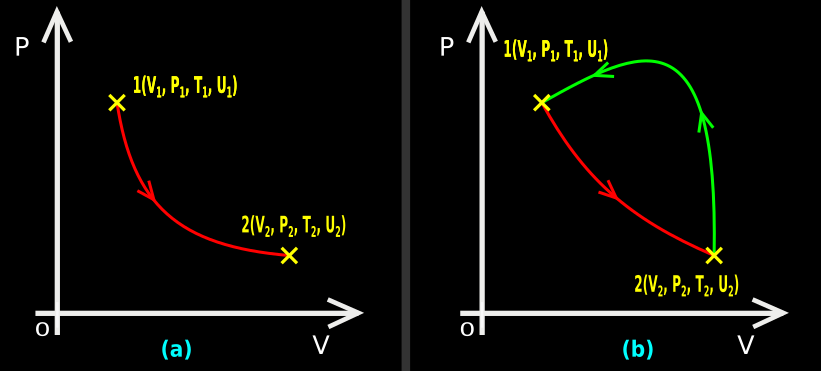
1. Consider fig.12.17 below
• It shows a cyclic process M-N-M
    ♦ The forward process M-N is along the green curve
    ♦ The backward process N-M is along the red curve

Thermodynamic cycles of refrigeration. It is the reverse of the cycles in heat engine.
Fig.12.17

2. In the forward process, volume of the gas decreases from VM to VN
    ♦ We can consider this as the downward motion of the piston
    ♦ So work is done on the gas during the forward process
3. In the backward process, volume of the gas increases from VN to VM
    ♦ We can consider this as the upward motion of the piston
    ♦ So work is done by the gas during the backward process
4. We can write:
    ♦ The piston starts from the extreme high point M
    ♦ Lowers down to the extreme low point N
    ♦ Returns to the extreme high point M
• This completes one cycle
5. Consider the forward process M-N
    ♦ Let the heat released by the gas during this process be QMN
    ♦
Let the work done on the gas during this process be WMN

• Then we get: UN = UM - QMN + WMN
⇒ UN - UM = -QMN + WMN

6. Consider the backward process N-M
    ♦ Let the heat absorbed by the gas during this process be QNM
    ♦
Let the work done by the gas during this process be WNM
• Then we get: UM = UN + QNM - WNM
⇒ UM - UN = QNM - WNM
7. Consider the results in (5) and (6)
• The left sides are numerically equal. Only difference is in the signs
8. Let us multiply both sides of (5) by '-1'
• We get: UM - UN = QMN - WMN
9. Now the left sides in (6) and (8) are the same
• So the right sides must be equal. We get:
QNM - WNM = QMN - WMN
⇒ WNM - WMN = QNM - QMN
Multiplying both sides by -1, we get:
WMN - WNM = QMN - QNM
10. Consider the left side of the result in (9):
    ♦ WMN is the work done on the gas when the piston moves down
    ♦
WNM is the work done by the gas when the piston moves up
• So (WMN - WNM) is the net work done on the gas
    ♦ We will denote this net work as W
    ♦ So we can write: W = WMN - WNM
11. Consider the right side of the result in (9):
    ♦ QMN is the heat released by the gas when the piston moves down
    ♦
QNM is the heat absorbed by the gas when the piston moves up
• So (QMN - QNM) is the net heat absorbed by the gas
12. From (9), we get Eq.12.11: W = QMN - QNM
• W is the net work done
• So it is clear that, the net work done is same as the net heat absorbed
 

Refrigerators

• We saw that, the gas receives a net work (W) and absorbs a net heat
• The 'net heat absorbtion' occurs when the piston completes one cycle
• If the cycle repeats continuously, we will get 'continuous absorbtion of heat'
• Such an arrangement which can produce 'continuous heat absorbtion' by receiving external work is called a refrigerator 

The main features of the refrigerator can be written in 6 steps:
1. In the refrigerator, all the molecules of the gas together form the ‘system’
2. We need to do work on this system. It can be done by compressing the gas using the piston
3. As a result of the work, the gas gives off heat (QMN) and becomes a liquid-vapour mixture
    ♦ Note that a suitable gas like freon must be used
    ♦ Such gases are called refrigerants
• QMN is given off into a hot reservoir which is kept at a temperature T1
(In practice, this hot reservoir is the 'space outside the refrigerator'. This space will be at room temperature)
4. When the downward motion of the piston is complete, ‘half of the first cycle’ is complete. We reach the point N
• Next we need to bring the piston to the original higher position M. Only then , can the gas be compressed in the next cycle
5. For that, the cylinder is placed in contact with the object to be cooled
• This object is called the 'cold reservoir'. It is at a temperature T2
• Heat QNM flows from this cold reservoir into the gas
• As a result, the gas expands and reaches the initial point M
• Now the piston is ready for the second cycle
(It is called the cold reservoir because, objects inside the refrigerator will be at a lower temperature. Even though the objects inside the refrigerator are cool, outside heat will penetrate through the walls of the refrigerator and try to warm the objects. We have to remove that heat which reaches the interior of the refrigerator)
6. The above steps can be schematically represented as shown in fig.12.18 below:

Schematic diagram of refrigerator or heat pump
Fig.12.18


 We see that:
    ♦ two items enter the system. They are: W and QNM
    ♦ one item leaves the system. It is: QMN
So QMN must be equal to (W + QNM)
Indeed, by rearranging Eq.12.11, we get: W + QNM = QMN
This implies that:
    ♦ The external work done (W)
    ♦ Plus
    ♦ The heat (QNM) removed from the 'object to be cooled'
    ♦ Gets dumped into the space surrounding the refrigerator
          ✰ When it is dumped, the system (gas) becomes ready for the next cycle

Coefficient of performance of a refrigerator

This can be explained in 3 steps:
1. If we can absorb 'more heat (QNM)' by doing a 'less net work (W)', we can say that, the coefficient of performance of the refrigerator is high
2. This coefficient is denoted using the symbol 𝛂
• Mathematically, we can write Eq.12.12: $\mathbf\small{\rm{\alpha=\frac{Q_{NM}}{W}}}$
• It is clear that, if QNM is high and W is low, 𝛂 will be high
3. Let us see the possible values of 𝛂:
It can be written in 4 steps:
(i) We have Eq.12.11: W = QMN - QNM
• This can be rearranged as: QNM = QMN - W
• So it is clear that W will be always less than QNM
• So $\mathbf\small{\rm{\frac{Q_{NM}}{W}}}$ will be always greater than 1
(ii) If the denominator W becomes smaller and smaller, the coefficient will become larger and larger
• If W becomes zero, the coefficient will become infinity. Such a refrigerator is not possible. We will see the reason in the next section
Since W cannot become zero, we can write:
It is impossible to remove heat from a body without doing external work W
(iii) We can derive another expression for 𝛂:
• Dividing both sides of Eq.12.11 by W, we get:
$\mathbf\small{\rm{1=\frac{Q_{MN}}{W}-\alpha}}$
⇒ $\mathbf\small{\rm{\alpha=\frac{Q_{MN}}{W}-1\;\;\;\;=\frac{Q_{MN}}{Q_{MN}-Q_{NM}}-1\;\;\;\;=\frac{Q_{MN}-Q_{MN}+Q_{NM}}{Q_{MN}-Q_{NM}}}}$
• Thus we get Eq.12.13: $\mathbf\small{\rm{\alpha=\frac{Q_{NM}}{Q_{MN}-Q_{NM}}}}$

Heat pump

Heat pumps are devices used to heat up the interior of a room when the surroundings of the room is cold
Heat pumps work in the same way as the refrigerators
A comparison can be written in 4 steps:
1. From where the heat is received:
In a refrigerator, system receives heat (QNM) from a cold body
    ♦ This cold body is the object to be cooled
In a heat pump also, the system receives heat (QNM) from a cold body
    ♦ This cold body is the surroundings of the room
2. Upon which the work is done:
In a refrigerator, external work (W) is done on the system
In a heat pump also, external work (W) is done on the system
3. To where the heat is dumped:
In a refrigerator, the ‘QNM + W’ is dumped into the surroundings of the refrigerator
In a heat pump, the ‘QNM + W’ is dumped into the interior of the room
4. Calculation of 𝛂:
In a refrigerator, the benefit that we receive, is the QNM removed from the body
    ♦ So we use the equation: $\mathbf\small{\rm{\alpha=\frac{Q_{NM}}{W}}}$
In a heat pump, the benefit that we receive, is the QMN available to heat the room
    ♦ So we use the equation: $\mathbf\small{\rm{\alpha=\frac{Q_{MN}}{W}}}$


In the next section, we will see the Carnot engine.

PREVIOUS

CONTENTS

NEXT

Copyright©2020 Higher Secondary Physics. blogspot.in - All Rights Reserved

Friday, January 22, 2021

Chapter 12.5 - The Heat Engine

In the previous section we saw the details about cyclic process. We saw the need to maximize the area enclosed by the curves. In this section, we will see how this can be achieved

Some basics can be written in 14 steps:
1. Consider the last fig.12.14 that we saw in the previous section
• It shows a cyclic process A-B-A
    ♦ The forward process A-B is along the red curve
    ♦ The backward process B-A is along the green curve
This is shown in fig.12.15 below also
2. In the forward process, volume of the gas increases from VA to VB
    ♦ We can consider this as the upward motion of the piston
    ♦ So work is done by the gas during the forward process
3. In the backward process, volume of the gas decreases from VB to VA
    ♦ We can consider this as the downward motion of the piston
    ♦ So work is done on the gas during the backward process
4. We can write:
    ♦ The piston starts from the extreme low point A
    ♦ Rises up to the extreme high point B
    ♦ Returns to the extreme low point A
• This completes one cycle
5. Consider the forward process A-B
    ♦ Let the heat absorbed by the gas during this process be QAB
    ♦
Let the work done by the gas during this process be WAB 
This is shown in fig.12.15 below:

Efficiency of a heat engine.
Fig.12.15

• Then we get: UB = UA + QAB - WAB
⇒ UB - UA = QAB - WAB
6. Consider the backward process B-A
    ♦ Let the heat released by the gas during this process be QBA
    ♦
Let the work done on the gas during this process be WBA
• Then we get: UA = UB - QBA + WBA
⇒ UA - UB = -QBA + WBA
7. Consider the results in (5) and (6)
• The left sides are numerically equal. Only difference is in the signs
8. Let us multiply both sides of (6) by '-1'
• We get: UB - UA = QBA - WBA
9. Now the left sides in (5) and (8) are the same
• So the right sides must be equal. We get:
QAB - WAB = QBA - WBA
⇒ WAB - WBA = QAB - QBA
10. Consider the left side of the result in (9):
    ♦ WAB is the work done by the gas when the piston moves up
    ♦ WBA is the work done on the gas when the piston moves down
• So (WAB - WBA) is the net work done by the gas
    ♦ We will denote this net work as W
    ♦ So we can write: W = WAB - WBA
11. Consider the right side of the result in (9):
    ♦ QAB is the heat absorbed by the gas when the piston moves up
    ♦ QBA is the heat released by the gas when the piston moves down
• So (QAB - QBA) is the net heat absorbed by the gas
12. From (9), we get Eq.12.8: W = QAB - QBA
• W is the net work
• So it is clear that, the net heat absorbed is converted into net work
13. Now, W is the area enclosed by the curves
• We want to maximize this area
• It is obvious from Eq.12.8 that:
For a given QAB, the net work W will be maximum when QBA is minimum
14. So we need to ensure that, the gas releases minimum possible heat
• Lesser the 'released heat', greater is the 'net work'

Heat engines

• We saw that, the gas receives heat and gives us a net work
• The net work is obtained when the piston completes one cycle
• If the cycle repeats continuously, we will get continuous work
• Such an arrangement which can produce continuous work by absorbing heat is called a heat engine
 

The main features of the heat engine can be written in 6 steps:
1. In the heat engine, all the molecules of the gas together form the ‘system’
2. We need to supply heat to this system. It can be done in any one of the two methods given below:
(i) Put the cylinder in contact with a heat reservoir at a high temperature T1
(ii) If the gas is combustible, ignite it using an electric circuit
3. As a result of the heat (QAB), the gas expands and does 'useful work' on the piston
• This piston can be connected to the wheels of an automobile
4. When the upward motion of the piston is complete, ‘half of the first cycle’ is complete
• Next, we need to bring the piston to it’s original lower position. Only then can the gas expand in the next cycle
5. For that, we push the piston downwards
• During this process, the cylinder is kept in contact with a cold reservoir at temperature T2
    ♦ So some heat (QBA) flows out of the system
• When the piston reaches the lowermost point, the ‘second half of the first cycle’ is complete
• Now the piston is ready for the second cycle
6. The above steps can be schematically represented as shown in fig.12.16 below:

Shematic diagram of a heat engine
Fig.12.16


We see that:
    ♦ one item enters the system. It is: QAB
    ♦ two items leave the system they are: W and QBA
So QAB must be equal to (W + QBA)
Indeed, by rearranging Eq.12.8, we get: W + QBA = QAB
This implies that
    ♦ part of QAB is converted into useful work
    ♦ the remaining part is released into the surroundings

Efficiency of a heat engine

This can be explained in 3 steps:
1. If we can obtain 'more useful work (W)' by supplying a 'less quantity of heat (QAB)', we can say that, the efficiency of the engine is high
2. Efficiency is denoted using the symbol 𝜼
• Mathematically, we can write Eq.12.9: $\mathbf\small{\rm{\eta=\frac{W}{Q_{AB}}}}$
• It is clear that, if W is high and QAB is low, 𝜼 will be high
3. Let us see the possible values of 𝜼:
It can be written in 4 steps:
(i) We have Eq.12.8: W = QAB – QBA
• So it is clear that W will be always less than QAB
• So $\mathbf\small{\rm{\frac{W}{Q_{AB}}}}$ will be always less than 1
• It will be a proper fraction. Engineers will be trying to obtain a high fraction like 9/10 or 95/100
(ii) We can derive another expression for 𝜼:
• Dividing both sides of Eq.12.8 by QAB, we get:
$\mathbf\small{\rm{\frac{W}{Q_{AB}}=\frac{Q_{AB}}{Q_{AB}}-\frac{Q_{BA}}{Q_{AB}}}}$
• Thus we get Eq.12.10: $\mathbf\small{\rm{\eta=1-\frac{Q_{BA}}{Q_{AB}}}}$
(iii) So it is clear that, if QBA is equal to zero, W will be equal to the absorbed heat
• That means, all the heat is converted into useful work
We will get 𝜼 = 1
(iv) This can be achieved if the 'heat released (QBA)' can be made zero
• But such an engine with 'efficiency 1' is not possible. We will see the reason in a later section


In the next section, we will see the reverse of the heat engine cycle


PREVIOUS

CONTENTS

NEXT

Copyright©2020 Higher Secondary Physics. blogspot.in - All Rights Reserved

Wednesday, January 20, 2021

Chapter 12.4 - Cyclic Process

In the previous section we saw the details about adiabatic process. In this section, we will see cyclic process

While learning about cyclic processes, we will be using a lot of P-V Diagrams. Also, we will need to carefully record internal energy changes. So we will first see how a P-V Diagram is related to the internal energy of the gas. Some basics can be written in 5 steps:

1. Consider any one point in the P-V Diagram. Let it be (V1, P1)
So, at that point, gas has a definite volume V1 and a definite pressure P1
2. In addition to definite volume and pressure at that point, the gas will have:
    ♦ a definite temperature T1
    ♦ a definite internal energy U1
3. So we can denote that point as (V1, P1, T1, U1)
4. When the gas is at another point 2, the values will be: (V2, P2, T2, U2)
This is shown in fig.12.12(a) below

Fig.12.12

5. Consider the last terms: U1 and U2
Initially the internal energy is U1
In that condition,
    ♦ We add heat Q to the gas or remove heat Q from the gas
    ♦ We do some work W on the gas or the gas does a work W
After the above Q and W interactions, U1 becomes U2 

Let us see a solved example which will demonstrate the above facts

Solved example 12.7
A gas is initially at point 1. It’s coordinates are: (V1, P1, T1, U1)
(a) When at point 1, a heat of 80 J is taken away from it. Also a work of 120 J is done on it. What is the ΔU experienced by the gas ?
(b) When at point 1, a heat of 90 J is added to the gas. What is the work done on/by gas? What is the ΔU experienced by the gas ?
(c) When at point 1, the gas does a work of 40 J. What is the heat added/taken? What is the ΔU experienced by the gas ?
(d) When at point 1, a work of 40 J is done on the gas. What is the heat added/taken? What is the ΔU experienced by the gas ?
Solution:
Part (a):
We have: U2 = U1 -80 +120
So ΔU = (U2 - U1) = 40 J
Part (b):
(i) Let us assume that, work is done on the gas
• We get: U2 = U1 +90 +W
⇒ ΔU = (U2 - U1) = (90 + W)
(ii) (V1, P1, T1, U1) and (V2, P2, T2, U2) are fixed values
⇒ U1 and U2 are fixed values
⇒ (U2 - U1) has a fixed value
⇒ ΔU has a fixed value
(iii) From part (a), we obtained ΔU as 40 J
• So the result in (i) becomes: 40 = 90 + W
• Thus we get: W = -50
(iv) This is a negative value. So our assumption (that work is done on the gas) in (i) is wrong
• We must write: U2 = U1 + 90 - W
• From this we get: 40 = ΔU = (U2 - U1) = (90 - W)
⇒ W = (90 - 40) = 50 J
• So the final answers are:
    ♦ ΔU = 40 J
    ♦ Gas does a work of 50 J
Part (c):
(i) Let us assume that, heat is added to the gas
• We get: U2 = U1 +Q -40
⇒ ΔU = (U2 - U1) = (Q - 40)
(ii) (V1, P1, T1, U1) and (V2, P2, T2, U2) are fixed values
⇒ U1 and U2 are fixed values
⇒ (U2 - U1) has a fixed value
⇒ ΔU has a fixed value
(iii) From part (a), we obtained ΔU as 40 J
• So the result in (i) becomes: 40 = Q - 40
• Thus we get: Q = 80
• So the final answers are:
    ♦ ΔU = 40 J
    ♦ Gas receives a heat of 80 J
Part (d)
:
(i) Let us assume that, heat is added to the gas
• We get: U2 = U1 +Q +40
⇒ ΔU = (U2 - U1) = (Q + 40)
(ii) (V1, P1, T1, U1) and (V2, P2, T2, U2) are fixed values
⇒ U1 and U2 are fixed values
⇒ (U2 - U1) has a fixed value
⇒ ΔU has a fixed value
(iii) From part (a), we obtained ΔU as 40 J
• So the result in (i) becomes: 40 = Q +40
• Thus we get: Q = 0
• So the final answers are:
    ♦ ΔU = 40 J
    ♦ No heat is added/taken
Note: In parts (b), (c) and (d) of this solved example, we were able to determine two unknown quantities. This is possible because, U1 and U2 are fixed quantities


Since U1 and U2 are fixed, we can arrive at an interesting result. It can be explained in 2 steps:
1. In fig.12.12(b) above,
    ♦ The gas first travels from point 1 to point 2 along the red path
    ♦ Then it travels from point 2 back to point 1 along the green path
2. When it reach back at point 1, it’s internal energy will be U1
So the net change in internal energy ΔU = U1 – U1 = 0

The following two solved examples will demonstrate the application of this fact
Solved example 12.8
A gas is initially at point 1 (V1, P1, T1, U1)
(a) When at point 1, a heat of 400 J is given to the gas. Also a work of 100 J is done by the gas. When these Q and W are effected, the gas reaches point 2 (V2, P2, T2, U2). What is the ΔU experienced by the gas while moving from 1 to 2
(b) From point 2, the gas is taken back to point 1. The Q and W during this process are not known. What is the ΔU experienced by the gas while moving from 2 to 1
(c) When at point 1, a work of 400 J is done on the gas. What is the heat Q added/taken? What is the ΔU experienced by the gas? Assume that, as a result of this '400 J work' and 'heat Q', the gas reaches point 2
Solution:
Part (a):
We have: U2 = U1 +400 -100 = U1 + 300
So ΔU = (U2 - U1) = 300 J
Part (b):
1. Let the unknown heat and work be Q and W
2. We have: U1 = U2 ±Q ±W
    ♦ '±' is given before Q because, we do not know whether heat is added or removed
    ♦ '±' is given before W because, we do not know whether work is done on the gas or by the gas
3. ΔU = (U1 - U2) = (±Q ±W)
• We cannot find ΔU using '(±Q ±W)' because, neither Q nor W is known
• But ΔU is equal to '(U1 - U2)'. The values of U1 and U2 will not change
    ♦ We have already calculated (U2 - U1) in part (a)
• Thus we get: ΔU = (U1 - U2) = -(U2 - U1) = -300 J
Part (c):
(i) Let us assume that, heat is added to the gas
• We get: U2 = U1 +Q +400
⇒ ΔU = (U2 - U1) = (Q + 400)
(ii) We have already calculated '(U2 - U1)' as 300 J
• So the result in (i) becomes: 300 = Q +400
• Thus we get: Q = -100 J
(iii) This is a negative value. So our assumption (that heat is added to the gas) in (i) is wrong
• We must write: U2 = U1 -Q +400
• From this we get: 300 = ΔU = (U2 - U1) = (-Q +400)
⇒ Q = (400 - 300) = 100 J
• So the final answers are:
    ♦ ΔU = 300 J
    ♦ Gas releases a heat of 100 J

Solved example 12.9
A gas is initially at point 1 (V1, P1, T1, U1). It expands and reaches point 2 (V2, P2, T2, U2). The path was along the red curve. See fig.12.13 below. To reach point 2 from point 1, an alternate path 1-3-2 is used. When this path is used, a heat of 515 J is to be added to the gas. How much heat will be required if the path 1-4-2 is used ? Given that:
P1 = 2.10 × 10⁵ N/m2, P2 = 1.05 × 10⁵ N/m2, V1 = 2.25 × 10⁻³ m3 and V2 = 4.5 × 10⁻³ m3

Internal energy in a PV diagram
Fig.12.13

Solution:
1. Consider the path 1-3-2
We have: U2 = U1 + 515 ±W
2. While moving from 1 to 3, volume expands. So work is done by the gas
Also, while moving from 3 to 2, volume remains the same. So no work is done
Thus, in effect, in the path 1-3-2, a work of W is done by the gas
So the sign of W in (1) is negative
We get: U2 = U1 + 515 - W
3. Our next task is to find W
The path 1-3 indicates an isobaric process
So work done = P ΔV = P1 (V2 - V1)
= 2.10 × 105 × (4.5 - 2.25) × 10-3 = 472.5 J
4. Substituting this W in (2), we get:
ΔU = (U2 - U1) = (515 - 472.5) = 42.5 J
5. Consider the path 1-4-2
We have: U2 = U1 ±Q ±W
6. While moving from 4 to 2, volume expands. So work is done by the gas
Also, while moving from 1 to 4, volume remains the same. So no work is done
Thus, in effect, in the path 1-4-2, a work of W is done by the gas
So the sign of W in (5) is negative
We get: U2 = U1 ± Q - W
7. Our next task is to find W
The path 4-2 indicates an isobaric process
So work done = P ΔV = P2 (V2 - V1)
= 1.05 × 105 × (4.5 - 2.25) × 10-3 = 236.25 J
8. Substituting this W in (6), we get:
ΔU = U2 - U1 = (± Q - 236.25)
9. But we already know ΔU from (4)
So we get: 42.5 = (± Q - 236.25)
10. Let us assume that, heat is added
Then the result in (9) becomes:
42.5 = Q - 236.25
Q = (42.5 + 236.25) = 278.75 J
11. This is a positive value. So the assumption made in (10) is correct
The final answer is:
When the gas moves along the path 1-4-2, a heat of 278.75 J should be added to the gas


Now we will see cyclic process. The basics can be written in 7 steps:
1. Fig.12.14(a) below shows a thermodynamic process from point A to point B
• The red arrows indicate that, volume increases from VA to VB
    ♦ So work is done by the gas
• We know that, this work is equal to the area below the red curve
    ♦ It is marked with magenta hatch lines

Area enclosed by the PV diagram curves is equal to the net work done by a cyclic thermodynamic process.
Fig.12.14


2. Fig.12.14(b) shows another thermodynamic process between the same points A and B
• But this time the process moves from point B to point A
• The green arrows indicate that, volume decreases from VB to VA
    ♦ So work is done on the gas
• We know that, this work is equal to the area below the green curve
    ♦ It is marked with grey hatch lines
3. Let us compare figs (a) and (b). The comparison can be written in 3 steps:
(i) The magenta area is larger than the grey area. That means:
    ♦ the work done by the gas
    ♦ is greater than
    ♦ the work done on the gas
(ii) This is an advantage because, we are receiving a 'net work'
• Obviously,
    ♦ this net work
    ♦ will be equal to
    ♦ the difference between the magenta and grey areas
(iii) The difference between the areas can be obtained by superimposing the grey area onto the magenta area. This is shown in fig.c
• We see that, the difference is equal to the area enclosed by the two curves
• So we can write:
    ♦ The net work done by the gas
    ♦ is equal to
    ♦ The area enclosed between the two curves
4. In fig.c, we see that:
• The process starts at A, moves to B and then moves back to A
    ♦ The movement from A to B is along the red curve
    ♦ The movement from B, back to A is along the green curve
5. Change in internal energy:
    ♦ When the gas is at A, it's internal energy is UA
    ♦ When the gas is back at A, it's internal energy is again UA
• So the change in internal energy = ΔU = (UA - UA) = 0
6. Now we apply the first law of thermodynamics for the whole process A-B-A:
• We have: ΔU = Q - W
Since ΔU is zero, we get:
The net work done by the gas is equal to the net heat absorbed by the gas
7. A cyclic process is the one which can be described using the above steps (4), (5) and (6)


We have seen that, the enclosed area gives the 'net work'. So our next task is to ‘maximize the enclosed area’. We will see how this can be achieved, in the next section


PREVIOUS

CONTENTS

NEXT

Copyright©2020 Higher Secondary Physics. blogspot.in - All Rights Reserved